In the current code base the main application performs a very simple task, it blinks an LED continuously until a user presses a button and then it stops. The blinking of the LED is implemented by a simple while loop and a delay. While in this loop, no other code can be executing, only the toggling of the LED. This is not a practical solution to performing a periodic task, which is a basic and common requirement of an embedded system. What if we also wanted to take a temperature measurement every 5 seconds. Trying to implement both of these using loops and delays would be complicated and most likely inaccurate. To address this issue, we will leverage what we learned about interrupts and implement a timer. Timers are a fundamental concept in embedded systems and they have many use cases such as executing a periodic task, implementing a PWM output or capturing the elapsed time between two events to name a few. Depending on the architecture, some timers may have specific purposes. For example, on ARM cores, there is a systick timer which is used to provide the tick for an operating system. On most ARM and Power Architecture cores, there is a PIT – periodic interval timer, which can be used for any type of periodic task. There are also timers used as a time base, i.e. to keep track of time for the system clock. At hardware level however, they pretty much operate using the same principle. The timer module has a clock input, which is often configurable (internal / external, clock divider etc..). On each clock pulse, the timer either increments or decrements the counter. When the counter reaches some defined value, an interrupt occurs. Once the interrupt is serviced, the timer may restart counting if it is a periodic timer, or it may stop until reconfigured. For timers used as a time base, the interrupt may not be required and the timer shall tick indefinitely and may be queried by software when required. To save resources, the MSP430 has combined most of this functionality into two timer modules – Timer_A and Timer_B. They share most of the same functionality, but there are some differences, notably that timer B can be configured to be an 8, 10, 12, or 16-bit timer while Timer_A is only a 16-bit timer. The other differences between Timer_A and Timer_B can be found in section 13.1.1 of the family reference manual. In this lesson, we will be using Timer_A to implement a generic timer module which can be used by the application to invoke periodic or one-shot timers. Then we will modify our application to replace the current implementation of the blinking LED to use timers so that in between blinking the LED the CPU can perform other tasks.
Timer_A theory
Before writing any code we must understand how Timer_A works and what registers are available to configure and control this peripheral. Timer_A is a 16-bit timer, which means it can increment to 0xFFFF (65536 cycles) before it rolls over. Both timers on the MSP430 have both capture and compare functionality. In fact, there are 3 timer blocks in Timer_A which can be independently configured to either mode. Capture functionality is used to time events, for example, the time between LED last toggled and the switch is pressed. In this scenario, the timer runs until one of these two events happen at which point the current value of the timer is stored in a capture register and an interrupt is generated. Software can then query the saved value and store it until the next interrupt is generated. The time difference between the two events can then be calculated in terms of ticks. A tick at the hardware level is one clock cycle, or the time between timer a increment or decrement. So if the timer was clocked at 1MHz, each tick would be 1us. The other mode which these timers support is compare mode, which is the standard use for a timer and the one we will be using in this lesson. Its is called compare mode because the timer value is compared against the interval assigned by software. When they match, the time has expired and an interrupt is generated. If the timer is configured as a periodic timer, it will restart the cycle again. The timer module has 3 modes which must be configured correctly for the specific application
- Up mode: timer will start with a value of zero and increment until a software defined value
- Continuous mode: timer will start at zero and increment until it rolls over at 0xFFFF
- Up/Down mode: timer will start at zero, increment until a defined value, and the start decrementing back to zero
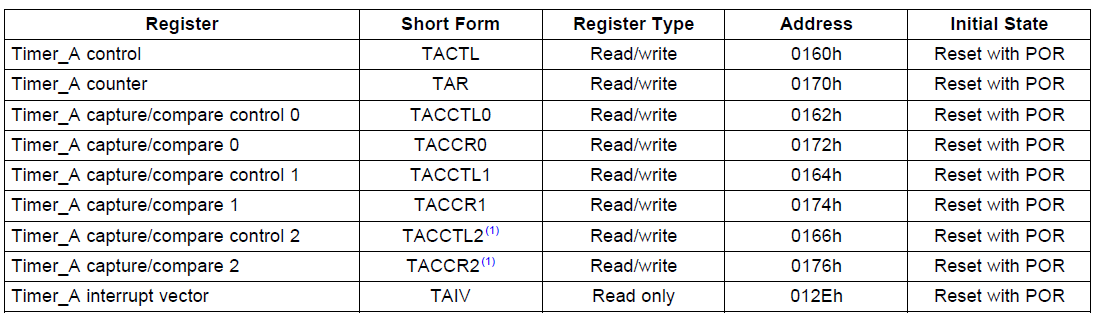
In our case, we will be be using the timer in up mode because we want to define an interval which is a minimum timer resolution for our application. Now lets take a look at how to configure Timer_A. The following table from the reference manual defines the registers associated with the module.
 TI MSP430x2xx Family Reference Manual (SLAU144J)
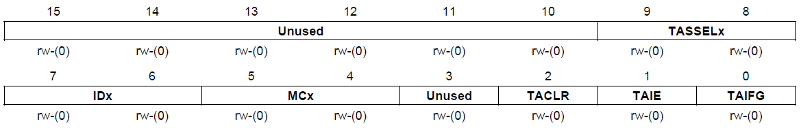
Timer_A control (TACTL) is the general timer control register. It is used to set up the timer clock source, divider clock mode and interrupts. The register definition is as follows:
 TI MSP430x2xx Family Reference Manual (SLAU144J)
- TASSELx: timer clock source select
- 00 TACLK (external Timer_A clock input)
- 01 ACLK
- 10 SMCLK
- 11 INCLK (device specific)
- IDx: input clock divider
- 00 /1
- 01 /2
- 10 /4
- 11 /8
- MCx: timer module mode control
- 00 Off (timer is halted)
- 01 Up mode
- 10 Continuous mode
- 11 Up/down mode
- TACLR: Timer_A clear
- 0 No action
- 1 Clear the current timer value as well as the divider and mode
- TAIE: Timer_A interrupt enable
- 0 interrupt disabled
- 1 interrupt enabled
- TAIFG: Timer_A interrupt flag
- 0 No interrupt pending
- 1 Timer interrupt pending
It is important to note that whenever modifying timer registers, it is recommended to halt the timer first using the TACLR bit, and then reset the register with the required parameters. This ensures that the timer does not expire unexpectedly and cause an interrupt or some other unintended consequence.
The Timer_A counter register (TAR) is the 16-bit register which contains the current value of the timer. Usually software would not have to read or write to this register unless it is being used as a time base. In most cases an interrupt would indicate when the timer expires, and since software must set the interval, the value of this register at that time would be known.
Timer_A capture/compare register x (TACCRx) and Timer_A capture/compare control register x (TACCTLx) are three pairs of the same registers. Remember earlier we saw that the Timer_A module has three capture / compare blocks that can be independently configured? These are the registers to do so. Software can utilize one, two or all three blocks simultaneously to perform different functions using a single timer. This make efficient use of the microcontroller’s resources since there is only one clock source and divider for all three. But each block can be configured to have a different timeout if in compare mode, or can be configure to capture mode. TACCRx is a 16-bit register which has two functions:
- Compare mode: the value set by software in this register will determine the interval at which the timer will expire when in up mode, or which the timer will start decrementing in up/down mode. If the timer is in continuous mode, this register has no effect on the interval. The value in this register is compared against that in TAR.
- Capture mode: this register will hold the value when the capture event occurs. The value from TAR is copied to this register to be read by software.
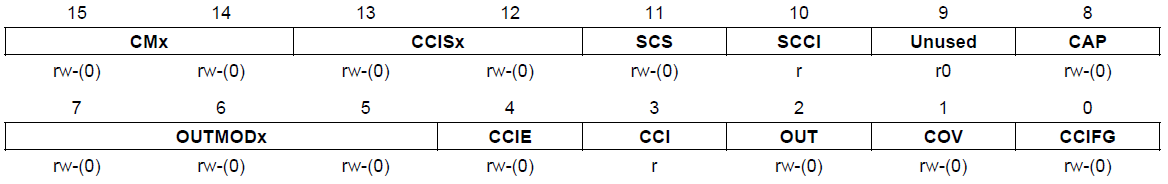
TACCTLx is the control register for each of the block and contains the following fields:
 TI MSP430x2xx Family Reference Manual (SLAU144J)
- CMx: capture mode – only valid when block is configured as a capture timer
- 00 No capture
- 01 Capture on rising edge of the timer clock
- 10 Capture on the falling edge of the timer clock
- 11 Capture on both edges of the timer clock
- CCISx: capture input selection – ie what input triggers the capture event
- 00 CCIxA (device specific)
- 01 CCIxB (device specific)
- 10 GND (ground)
- 11 Vcc
- SCS: synchronize capture input signal with the timer clock
- 0 Do not synchronize (asynchronous capture)
- 1 Synchronize the input with the timer (synchronous capture)
- SCCI: synchronized capture/compare input
- The latched value of the input at time of capture
- CAP: capture/compare mode selection
- 0 Compare mode
- 1 Capture mode
- OUTMODx: Timer_A can perform actions to specific output pins automatically in hardware (no ISR required). This field sets the desired action
- 000 OUT bit value (see below)
- 001 Set
- 010 Toggle/reset
- 011 Set/reset
- 100 Toggle
- 101 Reset
- 110 Toggle/set
- 111 Reset/set
- CCIE: capture/compare interrupt enable
- 0 Interrupt disabled
- 1 Interrupt enabled
- CCI: value of input signal of capture/compare module
- OUT: output value for OUTMODx = 000
- 0 Output is low
- 1 Output is high
- COV: capture overflow – timer overflowed before capture event occurs
- 0 No capture overflow
- 1 Capture overflow occured
- CCIFG: capture/compare interrupt flag
- 0 No pending interrupt
- 1 Interrupt is pending
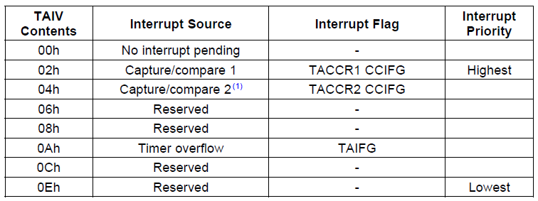
A few notes on this register. First is the concept of timer inputs and outputs. Each capture / compare block can select an input or output depending on the mode. In capture mode, an input is configured to trigger the capture. In compare mode, an output can be selected to toggle, clear, set an output pin etc.. upon timer expiry. The input is selected using the CCISx register. The pins for input/output must be configured correctly as indicated in the pin muxing table in the datasheet (remember lesson 4). Up to two inputs can be configured for the capture blocks – one at a time. The output pin is selected only through the pin muxing. The OUTMODx field is used to determine what action to take on the output pin. There are more details on what each of them mean in table 12-2 of the family reference manual. In this tutorial we will not be using these features, this is just a quick overview so that if you do need to use them you know where to start. The second point to discuss is that of interrupts. Each of the capture/compare blocks have their own separate interrupt enable and interrupt pending fields, in addition to the generic one for Timer_A in TACTL. There is a caveat however. Each of these blocks do not source their own interrupt vector. In fact, there is only two interrupt vectors for the whole module. The first is for TACCR0 which has the higher priority of the two. It also has the lowest interrupt latency, and requires the least processing in the ISR. Therefore this interrupt would be used in applications where accuracy of the timer is more important. This interrupt fires exclusively with TACCR0[CCIE] and cleared using TACCR0[CCIFG]. The rest of the interrupts all source the same IRQ called TAIV. It is not uncommon to package many interrupt sources into one IRQ and then provide a register which summarizes the all the flags. In the ISR, the software would read this register to determine the source, and respond accordingly. The TAIV register contains the source for the TAIV IRQ. The values defined for TAIV are as follows:
TI MSP430x2xx Family Reference Manual (SLAU144J)
Creating a timer library
As mentioned earlier, the goal of this tutorial is to replace the blinking LED loop with a timer in order to free up the CPU for other activities. The easiest and most efficient way to do so would be to use a timer which has configurable output to P1.0. We could then set the output mode to toggle and the interval set to 500ms and the LED would toggle automatically, no ISR required. Unfortunately, there is no output to P1.0 so we must write code to do it. However, instead of writing one interrupt handler to blink the LED, we will create a simple timer library which can be used to invoke multiple software timers / timeouts, both periodic or one-shot. This way, one single capture / compare block, as well as a single interrupt, can manage all the timers. Instead of setting the specific timer timeout in the TACCR0 register, the timer module will have a predefined tick interval. Each time the timer expires, the tick will be incremented. When a software timer is created from the application, its timeout will be calculated in terms of ticks (note this software tick is difference than the hardware tick mentioned earlier) relative to the current timer tick value. When the two are equal, it means that timer has expired and a callback function will be invoked. The timer library will have only three simple functions:
- timer_init: initialize the library the TIMER_A module and any internal data structures to be called from the board initialization routine – board_init
- timer_create: create a timer, set the timeout, periodic or single-shot, the callback routine and some private data
- timer_delete: stop and delete a timer
The implementation for our timer library will be extremely simple and therefore have some limitations. It is also definitely not the most efficient implementation, but the framework will be there to improve on if necessary. The use of a timer tick is pretty standard in most operating systems. The tick frequency is an important number to balance. If the tick is too fast, the program execution will be interrupted too often and may result in undesirable behaviour. On the other hand, if it is too slow, the timers may not have the required accuracy. A standard timer for normal operation will typically permit timeouts on the order of seconds down to milliseconds. For more accurate requirements in the range of microsecond or even nanoseconds there is typically a high speed timer, or auxiliary timer. Our timer library will have a resolution of 100ms. This means that every 100ms, the [software] timer will tick. It also implies that the minimum timeout would be 100ms, and anything not divisible by 100ms will have to be rounded. In this implementation, we will always round down, so the timer meets or exceeds its specified timeout.
To set up the timer module we have to consider a few things. First the timer module will be clocked using SMCLK, which is 1MHz. Therefore, we need to set the divider such that the timer doesn’t overflow before the required interval is attained. Remember the clock is 16 bits, so the maximum number of intervals is 65536. If the clock is not divided, there will be 1 million clock cycles per second. Therefore:

In 100 ms the counter would have to increment 

In 100ms the counter will increment 
The MSP430G2553 actually has two Timer_A modules, Timer_A3 and Timer1_A3 – where A3 means the time is a Timer_A type, and there are three capture compare blocks in each. This device has no Timer_B modules. The two timer A modules have their own assigned input and outputs as well as their own interrupt vectors. Looking at the datasheet under Table 5 – Interrupt Vector Addresses, you can see that Timer1_A3 has the higher priority. Since our timer API will need to be as efficient as possible in order to service multiple timers, it makes sense to take the one with the higher priority. This way, if Timer_A3 is ever implemented, or the watchdog is repurposed as a timer, this interrupt will always take priority. Also as mentioned earlier, each timer has two IRQs, one for the first block (TA1CCR0 CCIFG) interrupt, and another for the rest. Again, since we want to be as efficient as possible, we will use the former since it has the higher priority, less interrupt latency, and less instructions required to service the interrupt. We need the ISR to be as efficient as possible in order to service the timers as accurately as possible.
Lets start the implementation of the timer library. Our timer library will use a statically allocated list of timer data structures, up to some defined amount, say 10. Each data structure in the array must maintain some information about the timer when it is created, such as the duration, whether the timer is periodic or single shot, a pointer to the callback function, and some private data. The structure looks like this:
struct timer
{
    uint16_t expiry;
    uint16_t periodic;
    void (*callback)(void *);
    void *arg;
};

static struct timer _timer[MAX_TIMERS];
static volatile uint16_t _timer_tick = 0;
The expiry is the where the next expiry timeout will be stored in terms of timer ticks. The periodic member holds the duration in timer ticks of a periodic if set. Meaning, when the expiry time is met, the value stored in the periodic member can be added to the value of the current timer tick to obtain the next expiration value. Both these values are set as 16-bit unsigned integers, because our time tick will be of the same type. It would be nice to make it 32-bits in order to support longer timeouts, but the most efficient type to use on any machine is the native integer size. The callback function is self-explanatory, but the arg member is important. It is common practice when providing an interface with callbacks, to permit the storage of some data that is private to the caller. Another way of looking at it is like a cookie in your browser. A callback function may be used for multiple timers, so this data gives the callback function some context if needed. Making this member a void * means it could point to anything, even an integer, and the timer module has no idea what it contains.
The variable _timer_tick declared at the end of this code block is the software timer tick, which will be incremented every time the time module expires and an interrupt fires. Remember that volatile is required for variables which can be modified by an interrupt or outside the immediate scope to inform the compiler not to optimize out the read or write of the variable every single time. Since this variable is written by the ISR and will be read by the application, it is safest to declare it as volatile so that the compiler doesn’t optimize out the read and when the expiry is calculated it is done so correctly.
Next we write the function which configures the timer module as per the requirements previously discussed.
int timer_init(void)
{
    /* Clear the timer structure */
    memset(_timer, 0, sizeof(_timer));

    /* Set timer to use SMCLK, clock divider 2, up-mode */
    TA1CTL = TASSEL1 | ID0 | MC0;

    /* TA1CCR0 set to the interval for the desires resolution based on 1MHz SMCLK */
    TA1CCR0 = (((1000000 / 2) / 1000) * TIMER_RESOLUTION_MS) - 1;

    /* Enable CCIE interupt */
    TA1CCTL0 = CCIE;

    return 0;
}
First we clear the array of timers for good measure. Next timer module clock configuration is set to use SMCLK (1MHz) with the divider set to 2 (0.5MHz), and using up-mode. Remember, up-mode is used to count from zero up until the interval set in TA1CCR0. Because the counter is zero based, we must subtract one from the calculation of the number of ticks required for the desired timer resolution, in this case, 100ms. Finally we enable the timer interrupt by setting TA1CCL0[CCIE]. This function must be invoked before the timer library is used, so the best place to call it from is the board initialization. In the board_init function (src/board.c), the system clocks are configured. Once this is done, the timer module can be initialized.
/* Configure the clock module - MCLK = 1MHz */
DCOCTL = 0;
BCSCTL1 = CALBC1_1MHZ;
DCOCTL = CALDCO_1MHZ;

/* Configure ACLK to to be sourced from VLO = ~12KHz */
BCSCTL3 |= LFXT1S_2;

/* Initialize the timer module */
if (timer_init() != 0) {
    /* Timers could not be initialized...hang */
    while (1);
}
To create a new timer, we will write another function called timer_create. This function must take as arguments the desired timeout, a periodic or single-shot flag, the callback function, and the private data. The timeout will be in ms, but if the value passed in is less than the resolution, the timer will not fire accurately. The timeout will again be defined as a 16-bit unsigned integer, therefore the maximum timeout will be 65535ms which is 65s. Any value in between will be rounded to the nearest 100ms. Earlier we said we would always round down. The following explains why. There are really 3 options: 1) always round down 2) always round up and 3) round up if the remainder is greater than 50 otherwise round down. There are pros and cons to each of these. Always rounding down means that the timer may expire and the callback invoked earlier than requested. Always rounding up means that the timer may likely expire late. I would consider this to be the least desired functionality because in embedded systems there is often some time constraint that needs to be met (monitor a sensor every 50ms) which if not met, could have undesired consequences (we will talk more about real-time embedded systems in a later lesson). Rounding up or down depending on the remainder would be the most accurate, but it makes the assumption that if the timer is services ‘a bit late’, that it is acceptable. Again I consider this to be undesirable. Keep in mind, that no matter how well you code your timer library there will always be latency between when the timer expires and your callback is invoked due to the interrupt latency and ISR latency. Therefore, it is safest to expire early so we will always round down. However, this does leave one error case that must be accounted for: a timeout less than 100ms. In this case we have no option but to round up, since the period would be 0 timer ticks and expiring on the current timer tick would never happen. Lets take a look at the code.
int timer_create(uint16_t timeout_ms, int periodic, void (*callback)(void *), void *arg)
{
int handle = -1;
size_t i;
/* Find a free timer */
for (i = 0; i < MAX_TIMERS; i++) {
if (_timer[i].callback == NULL) {
break;
}
}
/* Make sure a valid timer is found */
if (i < MAX_TIMERS) {
SR_ALLOC();
ENTER_CRITICAL();
/* Set up the timer */
if (periodic != 0) {
_timer[i].periodic = (timeout_ms &lt; 100) ? 1 : (timeout_ms / TIMER_RESOLUTION_MS);
} else {
_timer[i].periodic = 0;
}
_timer[i].callback = callback;
_timer[i].arg = arg;
_timer[i].expiry = _timer_tick + _timer[i].periodic;
EXIT_CRITICAL();
handle = i;
}
return handle;
}
First we must find a free timer. Since there is a small number of timers, a simple linear search will suffice. A ‘NULL’ callback pointer is used to indicate a free timer, so the search is ended as soon as this condition is met. Now that we have found a free timer, we must elaborate on the concept of critical sections as briefly introduced in lesson 6 on Interrupts). Since the timer variables is accessed by both the application and the ISR, we must ensure that the operations which modify these variables from the application are atomic. If they are not, several bugs could present themselves. First, if the timer is still running, the timer tick could increment while the timer expiry is being calculated. This would result in an incorrect expiry. Even more seriously, if the application has filled out only part of the timer structure and the interrupt fires, the structure members may not be correct, and cause a timer to trigger prematurely, call an invalid function pointer, or pass an invalid argument to the function. Basically, as a rule of thumb, any variable(s) that are accessed by both the application and an ISR have to be locked by a critical section. A critical section does three things:
- saves the status register – this save the interrupt status
- disable interrupts
- restore the status register
Why do we do this rather than simply disabling and then enabling interrupts? What if interrupts are already disabled by some other part of the code and then we enter the critical section. When exiting, interrupts will be enabled, and therefore the state before and the state after are different. This is not correct, as they should be the same. The macros in the code above are implement as follow:
#define SR_ALLOC() uint16_t __sr
#define ENTER_CRITICAL() __sr = _get_interrupt_state(); __disable_interrupt()
#define EXIT_CRITICAL() __set_interrupt_state(__sr)
There are two new functions here, _get_interrupt_state and _set_interrupt_state, both of which are intrinsic to gcc. They can be found along with __disable_interrupt (which we have already used) in the file /opt/msp430-toolchain/msp430-none-elf/include/in430.h. These two functions read and write to the status register, where the global interrupt enable is set. The macro SR_ALLOC creates a variable __sr on the stack. ENTER_CRITICAL reads the current status register and saves it to this variable. Then interrupts are disabled. To exit the critical section and restore the previous state, EXIT_CRITICAL copies the saved value of the status register back into the register. As with ISRs, the length of the critical section is crucial to system performance. If the critical section is long, ISR may be missed or delayed. To minimize this, only the exact operation(s) which require locking should be in the critical section. In this case, any access to the global variables of the timer module should be wrapped in the critical section. The function returns a value which can be used to by the application to delete the timer. This will be called the timer handle, and will simply be the index of the timer being created. The timer_delete function is extremely simple, as it only has to clear the callback in order to disable the timer from being invoked. It is also wrapped in a critical section for good measure.
int timer_delete(int handle)
{
    int status = -1;

    if (handle < MAX_TIMERS) {
        SR_ALLOC();
        ENTER_CRITICAL();

        /* Clear the callback to delete the timer */
        _timer[handle].callback = NULL;

        EXIT_CRITICAL();
        status = 0;
    }

    return status;
}
You might wonder why this simple operation needs to be wrapped in a critical section. As it turns out, it doesn’t really because it will be compiled down to a single instruction which clears the memory. However, this is an assumption about the compiler, and not one that cannot always be made. In addition, it is possible that over time this time module evolves and the delete function required more in the implementation, so it is best practice to show that a critical section is required so that it isn’t forgotten later on.
The last component to our timer library is the ISR which handles the timer module expiry.
__attribute__((interrupt(TIMER1_A0_VECTOR))) void timer1_isr(void)
{
size_t i;
/* Clear the interrupt flag */
TA1CCTL0 &amp;= ~CCIFG;
/* Increment the timer tick */
_timer_tick++;
for (i = 0; i < MAX_TIMERS; i++) {
/* If the timer is enabled and expired, invoke the callback */
if ((_timer[i].callback != NULL) && (_timer[i].expiry == _timer_tick)) {
_timer[i].callback(_timer[i].arg);
if (_timer[i].periodic > 0) {
/* Timer is periodic, calculate next expiration */
_timer[i].expiry += _timer[i].periodic;
} else {
/* If timer is not periodic, clear the callback to disable */
_timer[i].callback = NULL;
}
}
}
}
First we must clear the interrupt flag so that the interrupt is cleared and the timer restarts counting. Next the timer tick is incremented and then compared against the expiry of each enabled timer in the array. If the timer is due, the callback is invoked with the private data passed in as the argument. Finally, if the timer is periodic, the next expiry is calculated, otherwise the timer is disabled by clearing the callback.
By creating our timer library, our code in main.c won’t have to deal in frequencies anymore, only in milliseconds, which is much easier and more portable. The timer library takes care of the conversion for us. The toggling of the output to the LED needs to be moved into the timer callback function. The whole delay in the while loop can be removed and replaced with the following code.
while (1) {
watchdog_pet();
/**
* If blinking is enabled and the timer handle is
* negative (invalid) create a periodic timer with
* a timeout of 500ms
*/
if (_blink_enable != 0 ) {
if (timer_handle &lt; 0) {
timer_handle = timer_create(500, 1, blink_led, NULL);
}
} else {
if (timer_handle != -1) {
timer_delete(timer_handle);
timer_handle = -1;
}
}
}
This will check if blinking is enabled, and if it is, it will create a timer to toggle the LED. The timer will be periodic with a timeout of 500ms. Once the timer is created, the timer handle will be non-negative, and therefore the while loop will continue on. If the blinking is disabled, the timer will be deleted. The callback function, blink_led, is a new function which toggles the LED. The existing code in the while loop to toggle the LED is moved into here. Note in this case we do not use the argument for any private data.
static void blink_led(void *arg)
{
    (void) arg;

    /* Toggle P1.0 output */
    P1OUT ^= 0x01;
}
Compile the latest code and program your launchpad. You should see that it behaves exactly as it did previously. To the user there is no difference, but the implementation allows us to have much more flexibility with our code. Now we can actually start using the while loop for other functions.
Hi Chris,
I am learning a lot going over this tutorial. However, when I compiled the downloaded code you created, I am getting a bunch of errors. I am coding for the MPS-EXP430F5529LP launchpad evaluation board using CCS V6.
This post talks about timers and there are compile errors related to this topic. Here are the problems listed related to this topic.
#20 identifier “CALBC1_1MHZ” is undefined
#20 identifier ” CALDCO_1MHZ” is undefined
#20 identifier “DCOCTL” is undefined.
These variables are listed in your post here and are in the file board.c Why are these not defined in this file or in the header file? Are they in a header file not listed? I am having a hard time understanding how these variables are defined and used. I am assuming they need to be defined someplace but I cannot find the location.
Other problems in this same list are the following:
#20 identifier “IE2″ is undefined uart.c
#20 identifier ” IFG1″ is undefined watchdog.c
#20 identifier “IFG2” is undefined uart.c
#20 identifier “LFXT1S_2″ is undefined board.c
#20 identifier ” P1SEL2″ is undefined board.c
#20 identifier “TLV_CHECKSUM” is undefined tlv.c
#20 identifier “UCA0RXIE” is undefined uart.c
#20 identifier “UCA0RXIFG” is undefined uart.c
#20 identifier “UCA0TXIFG” is undefined uart.c
#20 identifier “USCIABORX_VECTOR” is undefined uart.c
#20 identifier ” WDTSSEL” is undefined uart.c
It is very odd as I recognize some of these items from the User guide (SLAU208O.pdf) but again I do not understand where they are defined and why the code does not compile.
Could it be the build setting are wrong? Or maybe a version difference for CCS? I am programming for the MSP430F5529 using compiler TI MSP430 USB1.
Here is the compile error messages as well.
>> Compilation failure
subdir_rules.mk:49: recipe for target ‘uart.obj’ failed
“../uart.c”, line 94: error #20: identifier “IE2” is undefined
“../uart.c”, line 94: error #20: identifier “UCA0RXIE” is undefined
“../uart.c”, line 74: remark #1544-D: (ULP 13.1) Detected loop counting up. Recommend loops count down as detecting zeros is easier
“../uart.c”, line 74: remark #1544-D: (ULP 13.1) Detected loop counting up. Recommend loops count down as detecting zeros is easier
“../uart.c”, line 111: warning #69-D: integer conversion resulted in a change of sign
“../uart.c”, line 128: error #20: identifier “IFG2” is undefined
“../uart.c”, line 128: error #20: identifier “UCA0TXIFG” is undefined
“../uart.c”, line 128: remark #1527-D: (ULP 2.1) Detected SW delay loop using empty loop. Recommend using a timer module instead
“../uart.c”, line 149: error #20: identifier “IFG2” is undefined
“../uart.c”, line 149: error #20: identifier “UCA0TXIFG” is undefined
“../uart.c”, line 149: remark #1527-D: (ULP 2.1) Detected SW delay loop using empty loop. Recommend using a timer module instead
“../uart.c”, line 157: remark #1527-D: (ULP 2.1) Detected SW delay loop using empty loop. Recommend using a timer module instead
“../uart.c”, line 168: error #20: identifier “USCIAB0RX_VECTOR” is undefined
“../uart.c”, line 170: error #20: identifier “IFG2” is undefined
“../uart.c”, line 170: error #20: identifier “UCA0RXIFG” is undefined
9 errors detected in the compilation of “../uart.c”.
gmake: *** [uart.obj] Error 1
‘Building file: ../watchdog.c’
‘Invoking: MSP430 Compiler’
“C:/ti/ccsv6/tools/compiler/msp430_15.12.3.LTS/bin/cl430″ -vmspx –data_model=restricted –use_hw_mpy=F5 –include_path=”C:/ti/ccsv6/ccs_base/msp430/include” –include_path=”C:/ti/ccsv6/tools/compiler/msp430_15.12.3.LTS/include” –advice:power=all -g –define=__MSP430F5529__ –diag_warning=225 –diag_wrap=off –display_error_number –silicon_errata=CPU21 –silicon_errata=CPU22 –silicon_errata=CPU23 –silicon_errata=CPU40 –printf_support=minimal –preproc_with_compile –preproc_dependency=”watchdog.d” “../watchdog.c”
>> Compilation failure
subdir_rules.mk:56: recipe for target ‘watchdog.obj’ failed
“../watchdog.c”, line 52: error #20: identifier “IFG1” is undefined
“../watchdog.c”, line 70: error #20: identifier “WDTSSEL” is undefined
2 errors detected in the compilation of “../watchdog.c”.
gmake: *** [watchdog.obj] Error 1
gmake: Target ‘all’ not remade because of errors.
**** Build Finished ****
Hi Chris,
It is strange that those register/field definitions are not getting pulled in through CCS. Its been a while since I’ve used CCS, but I remember when you create a project it asks you to select a device. Based on the output, it looks like you have done that all correctly. I wonder though if the include path is correct. Can you trace down in CCS where the msp430.h header file takes you based on the define=__MSP430F5529__. I can’t imagine TI wrote a completely different header file for CCS and it looks like your missing _all_ the device specific definitions. There are a lot of people very familiar with CCS on TI’s E2E forums, so you might want to try there too.
is full code available?
All the code is available @ github.com/simplyembedded
How many interrupts from Timer A (compare mode) can be pending simultaneously? If the ISR for that interrupt is already being executed- but it gets delayed due to some reason. Now say there are 20 more interrupts from the same Timer A during that interval. What happens to those 20 interrupts? How many of these can be pending ??? Is it just 1 interrupt that can be pending as there is only 1 bit to indicate a pending interrupt and all other 19 interrupts are missed/ignored?
Hi Sahithya,
On the MSP430 only one interrupt can fire at a time. Interrupts will not pend if the flag is already set. However, as soon as the interrupt flag is cleared, another interrupt can fire, the flag will be set again, and as soon as the ISR exits, it will enter the ISR again. This is the reason why I stress that interrupts must be handled as quickly as possible. If the timer callback takes longer to execute than the period of the timer, than the following interrupt could be missed. This is a key part of the design and must be considered whenever designing an embedded system. Sometimes you have to know how many CPU cycles your ISR will take and determine if it can execute fast enough to allow other code to run too. If your ISR takes up all the CPU cycles, none of the other code will run either. Hence, as a rule of thumb, ISRs should never be allowed to get delayed. If your ISR can get delayed you will certainly run into problems – and they will almost definitely be intermittent and extremely difficult to catch and debug. The ISR must always be deterministic.
” Sometimes you have to know how many CPU cycles your ISR will take and determine if it can execute fast enough to allow other code to run too.”
How is that supposed to be done?
Its typically a feature of the toolchain. CCS might (?) have something like that. I think I have read that IAR does. I typically just look at the assembly output manually. For a small piece of code you can pretty easily calculate roughly how many cycle it will take. The number of cycles per instruction are documented in the family reference manual.
Hi
I’ve build and tried running lesson 8 and the led does not blink with a button pressed.
Here is my build output:
$ make
/opt/msp430-toolchain/bin/msp430-gcc -mmcu=msp430g2553 -c -Wall -Werror -Wextra -Wshadow -std=gnu90 -Wpedantic -MMD -Iinclude src/board.c -o build/obj/board.o
/opt/msp430-toolchain/bin/msp430-gcc -mmcu=msp430g2553 -c -Wall -Werror -Wextra -Wshadow -std=gnu90 -Wpedantic -MMD -Iinclude src/main.c -o build/obj/main.o
/opt/msp430-toolchain/bin/msp430-gcc -mmcu=msp430g2553 -c -Wall -Werror -Wextra -Wshadow -std=gnu90 -Wpedantic -MMD -Iinclude src/timer.c -o build/obj/timer.o
/tmp/ccpgXYhk.s: Assembler messages:
/tmp/ccpgXYhk.s:137: Warning: a NOP might be needed here because of successive changes in interrupt state
/tmp/ccpgXYhk.s:182: Warning: a NOP might be needed here because of successive changes in interrupt state
/opt/msp430-toolchain/bin/msp430-gcc -mmcu=msp430g2553 -c -Wall -Werror -Wextra -Wshadow -std=gnu90 -Wpedantic -MMD -Iinclude src/tlv.c -o build/obj/tlv.o
/opt/msp430-toolchain/bin/msp430-gcc -mmcu=msp430g2553 -c -Wall -Werror -Wextra -Wshadow -std=gnu90 -Wpedantic -MMD -Iinclude src/watchdog.c -o build/obj/watchdog.o
/opt/msp430-toolchain/bin/msp430-gcc -mmcu=msp430g2553 build/obj/board.o build/obj/main.o build/obj/timer.o build/obj/tlv.o build/obj/watchdog.o -o build/bin/app.out
Here is my mspdebug output:
$ mspdebug rf2500
MSPDebug version 0.18 – debugging tool for MSP430 MCUs
Copyright (C) 2009-2011 Daniel Beer
This is free software; see the source for copying conditions. There is NO
warranty; not even for MERCHANTABILITY or FITNESS FOR A PARTICULAR PURPOSE.
Trying to open interface 1 on 002
rf2500: warning: can’t detach kernel driver: No data available
Initializing FET…
FET protocol version is 30001000
Configured for Spy-Bi-Wire
Set Vcc: 3000 mV
fet: FET returned error code 4 (Could not find device (or device not supported))
fet: command C_IDENT1 failed
fet: identify failed
Trying again…
Initializing FET…
FET protocol version is 30001000
Configured for Spy-Bi-Wire
Sending reset…
Set Vcc: 3000 mV
Device ID: 0x2553
Device: MSP430G2553
Code memory starts at 0xc000
Number of breakpoints: 2
fet: FET returned NAK
fet: warning: message 0x30 failed
Available commands:
= delbreak gdb load opt reset simio
alias dis help locka prog run step
break erase hexout md read set sym
cgraph exit isearch mw regs setbreak
Available options:
color gdb_loop iradix
fet_block_size gdbc_xfer_size quiet
Type “help ” for more information.
Press Ctrl+D to quit.
(mspdebug) prog build/bin/app.out
Erasing…
Programming…
Writing 2 bytes to ffe4 [section: __interrupt_vector_3]…
Writing 2 bytes to fffa [section: __interrupt_vector_14]…
Writing 2 bytes to fffe [section: __reset_vector]…
Writing 4 bytes to c000 [section: .rodata]…
Writing 12 bytes to c004 [section: .rodata2]…
Writing 2156 bytes to c010 [section: .text]…
Writing 126 bytes to c87c [section: .data]…
(mspdebug) exit
Any idea what I’m missing?
Thanks…
DUH!!!
Sorry Chris, I just forgot to add
$ run
Now, as usual, it runs like a big bear 🙂
Mike
Hi, Thanks for the example, well explained.
However, there is a problem with the non-periodic mode, or maybe I am misunderstanding. If you set a non-periodic timer, the code in create_timer zeros out the timer[].periodic element and this is what is added to the expiry time, so in the case of non periodic mode, timer.expiry ends up the same as timer_tick.
This is the code I used to fix, added a temp variable;
temp = (timeout_ms < 100) ? 1 : (timeout_ms / TIMER_RESOLUTION_MS);
if (periodic != 0) {
_timer[x].periodic = temp;
} else {
_timer[x].periodic = 0;
}
_timer[x].callback = callback;
_timer[x].arg = arg;
// add expiry time, use temp here instead of timer[x].periodic
_timer[x].expiry = _timer_tick + temp;
That seemed to fix it.
Hi Chris. Yes you are absolutely correct. I had a patch which I never updated in the tutorial or the repo so thanks for pointing it out (and reminding me to update it)!
Make give the following warnings from the assembler. When I run the code it fails to interrupt on some button presses.
/opt/msp430-toolchain/bin/msp430-gcc -mmcu=msp430g2553 -c -Wall -Werror -Wextra -Wshadow -std=gnu90 -Wpedantic -MMD -I include -I /opt/msp430-toolchain/msp430-none-elf/include src/timer.c -o build/obj/timer.o
/tmp/ccD4ckAd.s: Assembler messages:
/tmp/ccD4ckAd.s:137: Warning: a NOP might be needed here because of successive changes in interrupt state
/tmp/ccD4ckAd.s:182: Warning: a NOP might be needed here because of successive changes in interrupt state
I looked around and found this:
https://e2e.ti.com/support/development_tools/compiler/f/343/t/649173
I don’t know if this is the problem of why it’s missing the occasional button presses, but figured I would forward it on. My hunch is the issue is with interrupt priorities. The timer is interrupting so much and with a much higher priority than the P1.3 button press the button press ISR can be missed often. I found a TI doc online that shows the interrupt priorities and PORT1 is much lower than TIMERA2.
https://courses.cs.washington.edu/courses/cse466/11au/calendar/04-Interrupts-posted.pdf
How would you solve this problem or deal with it from a design standpoint?
Learning a lot! Thanks!
Hi Chris,
Another question. Why is _timer not a volatile since it is being modified by the timer1_isr? Obviously, it works without being a volatile. I’m just wondering why that is?
Thanks!
Matt
Never mind! I figured it out. I didn’t fully understand the difference between critical and volatile. I reread Lesson 8 and 9 a few times. I think I got it now.
Thanks!