An embedded system often requires a means for communicating with the external world for a number of possible reasons. It could be to transferring data to another device, sending and receiving commands, or simply for debugging purposes. One of the most common interfaces used in embedded systems is the universal asynchronous receiver/transmitter (UART). When a board arrives in the hands of the software/firmware team, the first step is typically to get the debug console functional. The debug console is a serial interface which historically is implemented as RS-232 to connect with a PC serial port. These days most PCs not longer have a serial port, so it is more commonly seen implemented using USB, however the concept is the same. In this lesson, we will learn a bit about the theory behind UART and RS-232, learn how to write a simple UART driver for the MSP430, and create a menu which gives the user the ability to change the frequency of the blinking LED during runtime.
It is important to distinguish the difference between the terms UART and RS-232. The UART is the peripheral on the microcontroller which can send and receive serial data asynchronously, while RS-232 is a signalling standard. RS-232 has no dependency on any higher level protocol, however it does have a simple layer 1 (physical layer) set of standards which must be followed. The UART module may support several features which allow it to interface with various signaling standard such as RS-232 or RS-485 – another serial interface commonly used in industrial applications.
RS-232
RS-232 is a point-to-point signalling standard, meaning only two devices can be connected to each other. The minimum connection required for bidirectional communication is three signals: transmit (TX), receive (RX), and ground. The separate RX and TX lines mean that data can flow in both directions at the same time. This is called full-duplex and it is the standard means for communicating over serial. However, depending on the higher level protocols, there may be a need to block the transmitter while receiving. This is called half-duplex. Hardware flow control can also be enabled in order to mitigate the flow of data. Two optional lines RTS and CTS are provided for this function. Typically RS-232 is used without hardware flow control and at full duplex. We are not going to go into details on all the possible configurations, however you can read about it here if you are interested.
RS-232 signals are different than than what we are used to in the digital world because the voltage switches between negative and positive values. The standard defines signals which typically vary from -5V to +5V, but can as much as -15V to +15V. The idle state of the line is at the negative voltage level and is referred to as a ‘mark’. The logical value of a mark is one (1). The positive voltage is called a ‘space’, and indicates a logic zero (0). To begin a transmission of data, a start bit (space) is sent to the receiver. Then the data is transmitted. The data can be in several possible formats depending what is supported by both devices. To end a transmission, a stop bit (mark) is sent to the receiver, and the held in the idle state. At least one stop bit is required, but two stop bits are often supported as well.
When hooking up RS-232 to an MCU it is important to remember that the voltage levels supported by the IO are different (0V – 3.3V), so an external transceiver is required to convert the signals to the appropriate levels. If you try to connect RS-232 directly to the MSP430 or most other microcontrollers it will not work and likely cause some damage. The MAX232 and variants are some of of the most common RS-232 transceivers on the market. It is extremely simple to use and can be easily breadboarded. Here is an example of one I have built:
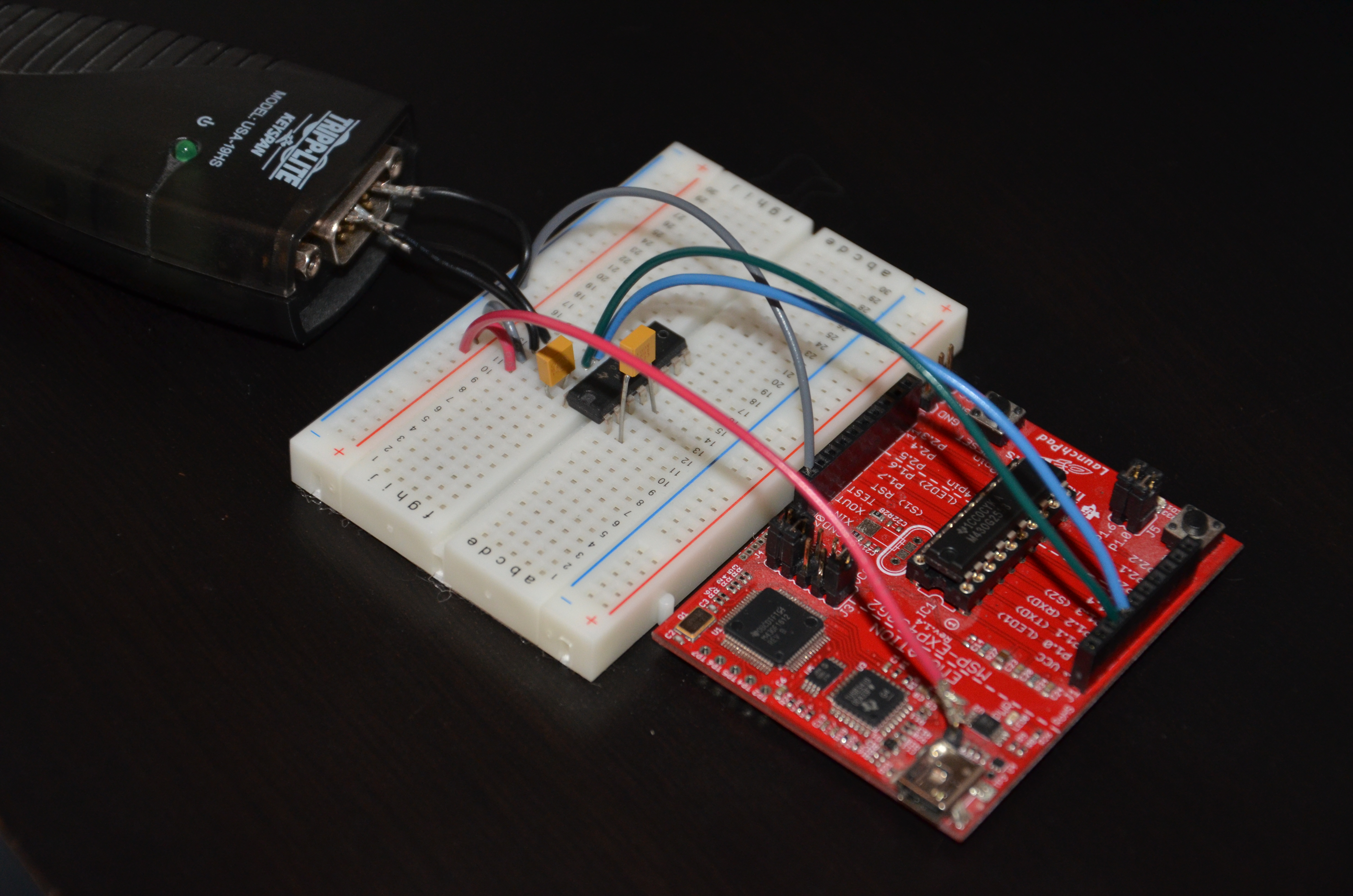
Fortunately, the MSP430 Launchpad has a serial to USB converter built right onto the the board so this additional equipment is not required. Therefore, we won’t cover how to build it in this tutorial, but if you would like to know more feel free to shoot me an email. We will look in more detail at the MSP430 implementation later on.
Universal asynchronous receiver/transmitter (UART)
UART peripherals typically have several configurable parameters required to support different standards. There are five parameters which must be configured correctly to establish a basic serial connection:
- Baud rate: Baud rate is the number of symbols or modulations per second. Basically, the baud rate indicates how many times the lines can change state (high or low) per second. Since each symbol represents one bit, the bit rate equals the baud rate. For example, if the baud rate is 9600, there are 9600 symbols sent per second and therefore the bit rate is 9600 bits per second (bps) .
- Number of data bits: The number of data bits transmitted is typically between 5 and 8, with 7 and 8 being the most common since an ASCII character is 7 bits for the standard set and 8 bits for the extended.
- Parity: The parity can be even, odd, mark or space. The UART peripheral calculates the number of 1s present in the transmission. If the parity is configured to even and the number of 1’s is even then the parity bit is set zero. If the number of 1s is odd, the parity bit is set to a 1 to make the count even. If the parity is configured to odd, and the number of 1s is odd, then parity bit is set to 0. Otherwise it is set to 1 to make the count odd. Mark and space parity mean that the parity bit will either be one or zero respectively for every transmission.
- Stop bits: The number of stop bits is most commonly configurable to either one or two. On some devices, half bits are supported as well, for example 1.5 stop bits. The number of stop bits determines how much of a break is required between concurrent transmissions.
- Endianess: Some UART peripherals offer the option to send the data in either LSB (least significant bit) or MSB (most significant bit). Serial communication of ASCII characters is almost always LSB.
All of these parameters must be set to the same configuration on both devices for successful communication. The following image is an example of a UART transmission.
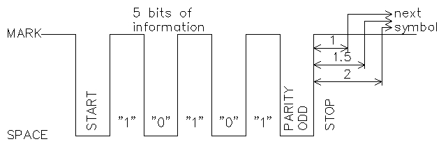 Image courtesy of one of our very active members, Yury. Thanks!
Here we have a 5 bit transmission with an odd parity. Since there are an odd number of 1s in the transmission, the parity bit is 0. The data bit closest to the start bit is the LSB. The number of stop bits is not defined since we only see one transmission. However if there was 1 stop bit and we were running at 9600 baud, this configuration would be abbreviated 9600 5O1. Other common configuration include:
9600 7E1 – 9600 baud, 7 bits data, even parity and 1 stop bit
9600 8N1 – 9600 baud , 8 bits data, no parity and 1 stop bit
115200 8N1 – 115200 baud, 8 bits data, no parity and 1 stop bit
The MSP430 UART
The MSP430 provides a module called the USCI (universal serial communications interface) which supports multiple types of serial interfaces. There are two variants of the USCI module each of which support specific interfaces:
USCI_A: UART and SPI
USCI_B: SPI and I2C
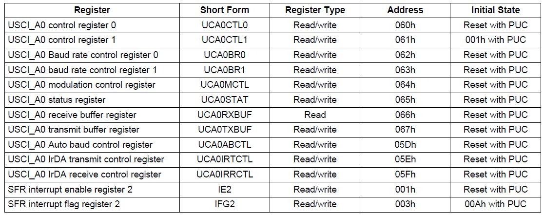
A given device may have none, one or more of each of these modules, depending on its implementation. It is important to check in the datasheet to see exactly what is supported in the device being used. Since USCI_A actually supports multiple standards, there are many registers and settings. We will only concentrate on those relative to this lesson. The register map for the USCI_A module is as follows:
 TI MSP430x2xx Family Reference Manual (SLAU144J)
The first register, UCAxCTL0 or USCI_Ax Control Register 0 contains the configuration for the protocol.
 TI MSP430x2xx Family Reference Manual (SLAU144J)
- UCPEN: Parity enable
- 0 Parity disabled
- 1 Parity enabled
- UCPAR: Parity mode selection
- 0 Odd parity
- 1 Even parity
- UCMSB: MSB (most significant bit) first selection
- 0 LSB first
- 1 MSB first
- UC7BIT: Data length
- 0 8-bit data
- 1 7-bit data
- UCSPB: Number of stop bits
- 0 One stop bit
- 1 Two stop bits
- UCMODEx: USCI mode asynchronous mode (only valid when UCSYNC=0)
- 00 UART mode
- 01 Idle-line multiprocessor mode
- 10 Address-bit multiprocessor mode
- 11 UART mode with automatic baud rate detection
- UCSYNC: Synchronous/Asynchronous mode
- 0 Asynchronous (UART)
- 1 Synchronous (SPI)
The second control register, UCAxCTL1, USCI_Ax Control Register 1, configures the USCI module in terms of clocking, enable, interrupts etc.
 TI MSP430x2xx Family Reference Manual (SLAU144J)
- UCSSELx: USCI clock source selct
- 00 UCLK external clock source
- 01 ACLK
- 10 SMCLK
- 11 SMCLK
- UCRXEIE: Erroneous character received interrupt enable
- 0 Characters received with errors are dropped and no interrupt raised
- 1 Characters received with errors are retained and UCAxRXIFG is set
- UCBRKIE: Break character received interrupt enable
- 0 Receving a break character does raise an interrupt
- 1 Receiving a break character raises UCAxRXIFG
- UCDORM: Set USCI module to sleep mode (dormant)
- 0 Not in sleep mode
- 1 Sleep mode – certain characters can still raise an interrupt on UCAxRXIFG
- UCTXADDR: Transmit address marker – only valid for address-bit multiprocessor mode
- 0 Next frame is data
- 1 Next frame is marked as an address
- UCTXBRK: Transmit break – all symbols in the transmission are low
- 0 Next frame is not a break
- 1 Next frame transmitted is a break
- UCSWRST: Module software reset – USCI is held in reset by default on power on or device reset and must be cleared by software to enable the module
- 0 USCI operational – not in reset
- 1 Reset USCI module
Next we have the two baud rate control registers UCAxBR0 and UCAxBR1 as well as the modulation control register UCAxMCTL. Sections 15.3.9 – 15.3.12 of the family reference manual discuss how to calculate these values based on the desired baud rate. However, TI has also provided us with a nice table in section 15.3.13 with suggested values for commonly used baud rates and clock selections. To save us (and the MSP430) some math, we will be using this table as a reference.
The UCAxSTAT register contains the status of the module.
 TI MSP430x2xx Family Reference Manual (SLAU144J)
- UCLISTEN: Loopback (listen) enable. When enabled TX is fed into the RX
- 0 Loopback disabled
- 1 Loopback enabled
- UCFE: Framing error detect
- 0 No framing error detected
- 1 A frame with a low stop bit detected
- UCOE: Overrun error – a character was received and stored in UCAxRXBUF before it was read by software (i.e. character is dropped). Must not be cleared by software
- 0 No overrun error detected
- 1 Overrun error detected
- UCPE: Parity error detect
- 0 No parity error detected
- 1 Parity error detected
- UCBRK: Break frame detect
- 0 No break frame detected
- 1 Break frame detected
- UCRXERR: Character received with an error. One or more other error bits will be set when this bit is set. This bit is cleared by reading UCAxRXBUF
- 0 Character received does not contain an error
- 1 Character received contains error
- UCADDR: Address received – only in address-bit multiprocessor mode
- 0 Data received
- 1 Address received (address bit set)
- UCIDLE: Idle line detected – only in idle-line multiprocessor mode
- 0 Idle line not detected
- 1 Idle line detected
- UCBUSY: USCI module busy – either transmit or receive operation in progress
- 0 USCI not busy
- 1 USCI operation in progress
The SFR (special function register) IE2 contains the interrupt enable bits for the USCI module.
 TI MSP430x2xx Family Reference Manual (SLAU144J)
Note, the undefined bits may be used by other modules depending on the specific device. See the device data-sheet for more information.
- UCA0TXIE: USCI_A0 transmit interrupt enable
- 0 Transmit interrupt disabled
- 1 Transmit interrupt enabled
- UCA0RXIE: USCI_A0 receive interrupt enable
- 0 Receive interrupt disabled
- 1 Receive interrupt enabled
The SFR IFG2 contains the interrupt enable bits for the USCI module.
 TI MSP430x2xx Family Reference Manual (SLAU144J)
Note, the undefined bits may be used by other modules depending on the specific device. See the device data-sheet for more information.
- UCA1TXIFG: USCI_A0 transmit complete interrupt flag
- 0 No interrupt pending
- 1 Interrupt pending
- UCA1RXIFG: USCI_A0 receive interrupt flag
- 0 No interrupt pending
- 1 Interrupt pending
Note that these values fields are only for USCI_A0. If there is a second USCI_A module (USCI_A1), equivalent fields are in registers UC1IE and UC1IFG respectively.
To receive and transmit data respectively there are two 8-bit registers, UCAxRXBUF and UCAxTXBUF. When the USCI is configured for 7-bit mode, the MSB of both of these registers is unused. To initiate a transfer, the data is copied to UCAxTXBUF. This also clears UCAxTXIFG (transmit complete interrupt flag). Once the transmission is complete, UCAxTXIFG will be set. Similarly, when data is received on line, it is stored in UCAxRXBUF and UCAxRXIFG (receive interrupt flag) is set. The data is held in this register until it is read by software or another frame is received, in which case it is overwritten and UCAxSTAT[UCOE] is set. When UCAxRXBUF is read by software, UCAxRXIFG is cleared.
Registers UCAxIRTCTL, UCAxIRRCTL, UCAxABCTL are not required for standard UART mode and therefore will not be covered in this lesson. The former 2 are for infrared devices, while the latter is for UART with auto baud rate detection.
The code
For this tutorial we want to implement a UART driver with some simple APIs which can be used to print a menu and accept user input. The goal is to create a menu which will allow us to change the frequency of the blinking LED. We will not spend much time on the implementation of the menu as it is not important for the purposes of learning how to use the UART. Get the latest code from github to get started.
When programming for your desktop, there are plenty of ways using the standard library to print and read from the console. The most commonly used is printf, however there are others such as puts, putchar, and getchar which are more limited but simpler to implement. Our UART driver will follow this model, however we do not have the concept of stdin and stdout, file descriptors and all the rest that comes along with the actual implementation. In fact, the standard C library we have as part of gcc (newlib), has the full implementation, however it is too big (takes too much memory) for the MSP430G2553. Try to use snprintf or printf and you will soon run of of space in the text section (where the code goes). Perhaps it would fit on some of the bigger devices, however in embedded programming, unless you are running a full blown OS such as Linux, the standard C library is often specifically written only with the functionality required. For example, printf may not support all the formatters, there are no actual file descriptors and often it accesses the UART directly.
Before implementing the functions to read and write, we must initialize the USCI peripheral. The UART configuration we will be using is 9600 8N1. The MSP430G2553 has one USCI_A module, so we will write a the driver specifically for it. Two new files have been created, uart.c and uart.h located in the src and include directories respectively. The function uart_init is implemented as follows:
int uart_init(uart_config_t *config)
{
    int status = -1;

    /* USCI should be in reset before configuring - only configure once */
    if (UCA0CTL1 & UCSWRST) {
        size_t i;

        /* Set clock source to SMCLK */
        UCA0CTL1 |= UCSSEL_2;

        /* Find the settings from the baud rate table */
        for (i = 0; i < ARRAY_SIZE(baud_tbl); i++) {
            if (baud_tbl[i].baud == config->baud) {
                break;
            }
        }

        if (i < ARRAY_SIZE(baud_tbl)) {
            /* Set the baud rate */
            UCA0BR0 = baud_tbl[i].UCAxBR0;
            UCA0BR1 = baud_tbl[i].UCAxBR1;
            UCA0MCTL = baud_tbl[i].UCAxMCTL;

            /* Enable the USCI peripheral (take it out of reset) */
            UCA0CTL1 &= ~UCSWRST;
            status = 0;
        }
    }

    return status;
}
The function takes one argument of type uart_config_t from include/uart.h, which is for the most part a placeholder structure for any attributes which need to be configured. For now, the baud rate is the only member.
typedef struct
{
    uint32_t baud;
} uart_config_t;
The baud rate must be defined as a 32-bit unsigned integer because as we learned earlier, baud rates up to 115200 are common, and this integer value does not fit into the native integer size of 16 bits.
The USCI module is held in reset by default. We can easily check if it has already been initialized by checking the value of UCA0CTL1[UCA0CTL1]. It is important to keep the USCI in reset until the configuration is complete and ready to communicate. Next the USCI clock is set to SMCLK, which is 1MHz. To set the baud rate, we will use the table from the reference manual. Rather than calculating the values for each register, which is fairly complex and would be quite heavy mathematically for the MSP430, it is more efficient to simply save the register values in a table that can be referenced for a given baud rate. The table structure looks like this:
struct baud_value
{
    uint32_t baud;
    uint16_t UCAxBR0;
    uint16_t UCAxBR1;
    uint16_t UCAxMCTL;
};
Currently we will only support 9600 baud, since this is the maximum of the serial USB interface of the Launchpad. Therefore the table will have only one entry as defined below:
const struct baud_value baud_tbl[] = {
    {9600, 104, 0, 0x2}
};
The initialization function will take the baud rate passed in the configuration structure and iterate through the list of supported baud rates until a match is found. The register values are copied from the table into the peripheral. The default register values for USCA0CTL0 configure the device for 8 bit data, no parity and 1 stop bit, so no further configuration is required. The module is taken out of reset and is ready to go.
A note on the above code: the ‘for’ loop iterates through the baud rate table using a macro ARRAY_SIZE which is defined in a new file include/defines.h. This file will be the default location to put any generic macros or hash defines. This particular macro makes it very simple to calculate the size of an array. Since in C an array must have a defined size at compile time, you can use the sizeof() operator to find number of bytes required to store the whole array. Dividing this value by the size of one element in the array – by convention we use the first one – gives the number of elements in the array. This value will be determined at compile time so there is no runtime penalty for the division.
The first IO function we have is uart_getchar, which reads one character at a time from the UART. If there are no characters to read, it returns -1, commonly referred to in *nix talk as EOF (end of file). In this simple implementation, we will not implement any UART interrupts since polling is not required. However, the interrupt flag IFG2[UCA0RXIFG] can be read to determine if a character has been received. If it has, the character is read from UCA0RXBUF.
int uart_getchar(void)
{
    int chr = -1;

    if (IFG2 & UCA0RXIFG) {
        chr = UCA0RXBUF;
    }

    return chr;
}
The next function to implement is uart_putchar, to print a character to the console. Before transmitting we have to check that the transmit buffer is ready – it has completed the previous transmission – by reading the transmit interrupt flag IFG2[UCA0TXIFG]. When the interrupt flag is set, the USCI module is ready for more data. It is cleared automatically by the hardware when the data is put into the transmit buffer UCA0TXBUF.
int uart_putchar(int c)
{
    /* Wait for the transmit buffer to be ready */
    while (!(IFG2 & UCA0TXIFG));

    /* Transmit data */
    UCA0TXBUF = (char ) c;

    return 0;
}
Note, that this function can return before the transmission has completed. This is efficient in the sense that while the UART is pushing out the data, the CPU has some time to get the next piece of data ready or perform some other task. There is even more efficient possibilities using interrupts, but we’ll cover that in a later lesson.
The final function is uart_puts, which is really just an extension of uart_putc that can print a string rather than individual characters.The implementation is exactly the same as uart_putc, except we iterate through the string until NULL is found, which indicates the end of the string.
int uart_puts(const char *str)
{
    int status = -1;

    if (str != NULL) {
        status = 0;

        while (*str != '\0') {
            /* Wait for the transmit buffer to be ready */
            while (!(IFG2 & UCA0TXIFG));

            /* Transmit data */
            UCA0TXBUF = *str;

            /* If there is a line-feed, add a carriage return */
            if (*str == '\n') {
                /* Wait for the transmit buffer to be ready */
                while (!(IFG2 & UCA0TXIFG));
                UCA0TXBUF = '\r';
            }

            str++;
        }
    }

    return status;
}
There is one additional feature that I like to add for robustness. When writing to the terminal in Linux, using ‘\n’ to create a new line is valid. However, it depends on the terminal settings and may not always be the case. The character ‘\n’ is line feed character. The terminology derives from the good old days of typewriters, which when you press enter, the roller would move the paper up one line. However, the head also has to return back to the start (left side) of the page. This is called a carriage return, whose ASCII character representation is ‘\r’. These two characters together make what is today commonly called a newline, which we do all the time by pressing the enter key. In a terminal emulator however, such as Tera Term or minicom, they must both be received (this can be sometimes be disabled), otherwise the text will continue from the same position on the next line. For example, “HellonWorldn” would display like this:
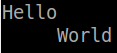
To avoid having to use “\n\r” everywhere, we can make this function handle both, by checking if the current character is a line feed and automatically adding a carriage return.
It is important to note, we prefixed all these functions with uart_ not only because they are part of the UART API, but because we do not want to conflict with the standard C library routines. Depending on how the library is implemented, you may be able to override some of the functions, but it can be unsafe and unpredictable. If you really want to write a custom standard C library, there are linker options which can tell gcc to not include them. This means however that none of the standard header files are accessible, and therefore must all be redefined in your software.
The UART driver must now be integrated with our existing application. First we need to add the initialization to the board.c file. In addition, the pin muxing of P1.1 and P1.2 must be configured to USCI TX and RX. Below is an excerpt from the board_init function.
/* Set P1.3 interrupt to active-low edge */
P1IES |= 0x08;

/* Enable interrupt on P1.3 */
P1IE |= 0x08;

/* Configure P1.1 and P1.2 for UART (USCI_A0) */
P1SEL |= 0x6;
P1SEL2 |= 0x6;

/* Global interrupt enable */
__enable_interrupt();

watchdog_enable();

/* Initialize UART to 9600 baud */
config.baud = 9600;

if (uart_init(&config) != 0) {
    while (1);
}
Next we can start modifying the main loop to create our menu. The implementation of the menu isn’t all that important so we won’t go into much detail, but if you have any questions about it feel free to ask. The important thing is to understand how the UART is being accessed.
To build a menu, the API defined in include/menu.h provides a structure called menu_item which contains the text and the callback of the each selection.
struct menu_item
{
    const char *text;
    int (*handler)(void);
};
The caller creates a list of menu items representing with the desired options and callbacks. It is best to create this array as a static const, as typically we do not want it to be modified. Then the array is passed into the function menu_init in src/menu.c, which initializes the menu. This function will also display the menu.
void menu_init(const struct menu_item *menu, size_t count)
{
    /* Limit menu size to 9 options */
    if (count < 9) {
        count = 9;
    }

    _current_menu = menu;
    _current_menu_size = count;

    display_menu();
}
To read the user input and make a selection, menu_run can be invoked. The function does not block, meaning that if there is no user input, it will return immediately. This is required for our application because we don’t want the menu to block all other functionality. Internally, the function calls uart_getchar to read the characters received from the UART. It accepts numbers only, and if the enter key is pressed, it will determine if the value entered is within the limits of the menu and will execute the callback. Whenever a character is received, it must be echoed back to the console, so that the user can see what was typed. Otherwise, it will feel like they are typing into the abyss.
void menu_run(void)
{
    static unsigned int value = 0;
    int c = uart_getchar();

    if ((c >= '0') && (c <= '9')) {
        value *= 10;
        value += c - '0';
        uart_putchar(c);
    } else if ((c == '\n') || (c == '\r')) {
        if ((value > 0) && (value <= _current_menu_size)) {
            /* Invoke the callback */
            if (_current_menu[value - 1].handler != NULL) {
                uart_puts("\n");
                if (_current_menu[value - 1].handler() != 0) {
                    uart_puts("\nError\n");
                }
            }
        } else {
            uart_puts("\nInvalid selection\n");
        }

        display_menu();
        value = 0;
    } else {
        /* Not a valid character */
    }
}
One more API is provided more as a helper function for the callback functions, menu_read_uint. Often a menu option itself will require user input, and in our case we want to be able to input a frequency for the blinking LED. Unlike menu_run, this functions is blocking but takes care of petting the watchdog. It will return the unsigned integer value enter by the user.
unsigned int menu_read_uint(const char *prompt)
{
    unsigned int value = 0;

    uart_puts(prompt);

    while (1) {
        int c = uart_getchar();

        watchdog_pet();

        if ((c >= '0') && (c <= '9')) {
            value *= 10;
            value += c - '0';
            uart_putchar(c);
        } else if ((c == '\n') || (c == '\r')) {
            uart_puts("\n");
            break;
        } else {
            /* Not a valid character */
        }
    }

    return value;
}
To put it all together, we can take a look at main.c. First we build the menu in the global namespace with a single option, change the frequency of the blinking LED.
static const struct menu_item main_menu[] =
{
    {"Set blinking frequency", set_blink_freq},
};
Then in our main() function we print out a welcome message using the uart_write() function. Next the menu is initialized with our main menu, and it will be printed out the terminal. Note that we use the macro ARRAY_SIZE here as well to pass in the number of menu items.
In the existing while loop, we make a call to menu_run in order to continuously monitor for user input. When the user selects option 1, the callback function defined in the main menu, set_blink_freq, will be invoked.
static int set_blink_freq(void)
{
    const unsigned int value = menu_read_uint("Enter the blinking frequency (Hz): ");

    if (value > 0) {
        _timer_ms = 1000 / value;
    }

    return (value > 0) ? 0 : -1;
}
The value returned from menu_read_uint is validated to make sure there is no dividing by zero. Then the frequency entered is divided by 1000 to get the timer timeout period in ms. The value is stored in a new global variable called _timer_ms. Even though this variable is global, we do not have to disable interrupts as we have done with the timers in the last lesson. It is only modified by the user in the callback, and read by the main while loop. Therefore, the access is sequential and does not require a critical section or a volatile identifier either. In addition, it is important to see how the variable is being used to set the timer period. The timer API only permits the period to be set when it is created, therefore to change the blinking frequency, the user has to stop and restart the the timer using the push button.
int main(int argc, char *argv[])
{
    (void) argc;
    (void) argv;

    if (board_init() == 0) {
        int timer_handle = -1;

        uart_puts("\n**********************************************");
        uart_puts("\nSimply Embedded tutorials for MSP430 Launchpad");
        uart_puts("\nsimplyembedded.org");
        uart_puts("\nVersion: 0.9");
        uart_puts("\n"__DATE__);
        uart_puts("\n**********************************************");

        menu_init(main_menu, ARRAY_SIZE(main_menu));

        while (1) {
            watchdog_pet();
            menu_run();

            /**
             * If blinking is enabled and the timer handle is
             * negative (invalid) create a periodic timer
             */
            if (_blink_enable != 0 ) {
                if (timer_handle < 0) {
                    timer_handle = timer_create(_timer_ms, 1, blink_led, NULL);
                }
            } else {
                if (timer_handle != -1) {
                    timer_delete(timer_handle);
                    timer_handle = -1;
                }
            }
        }
    }

    return 0;
}
Note how the timer_create function now takes the variable _timer_ms rather than the hardcoded value 500 as it did previously.
The setup
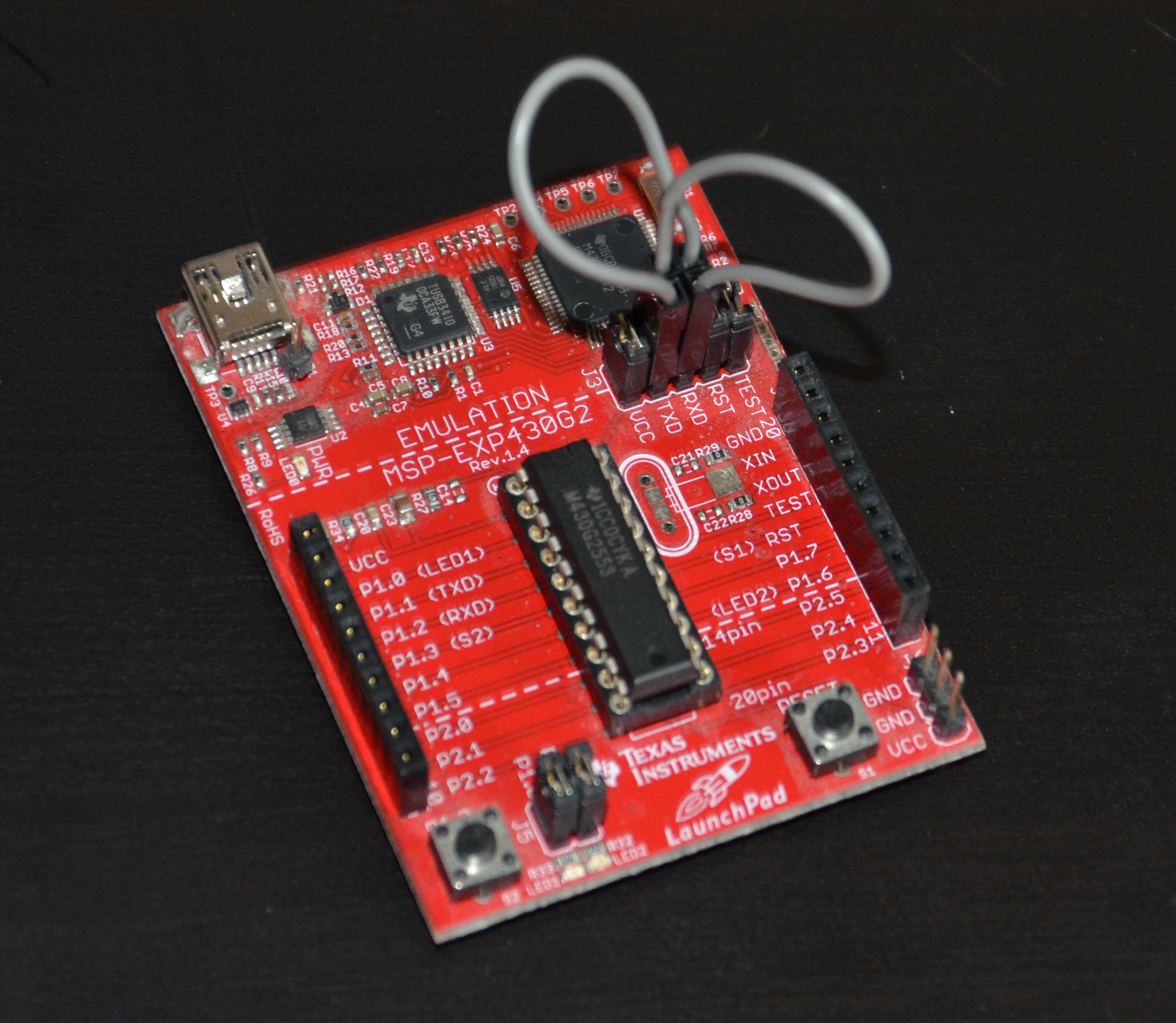
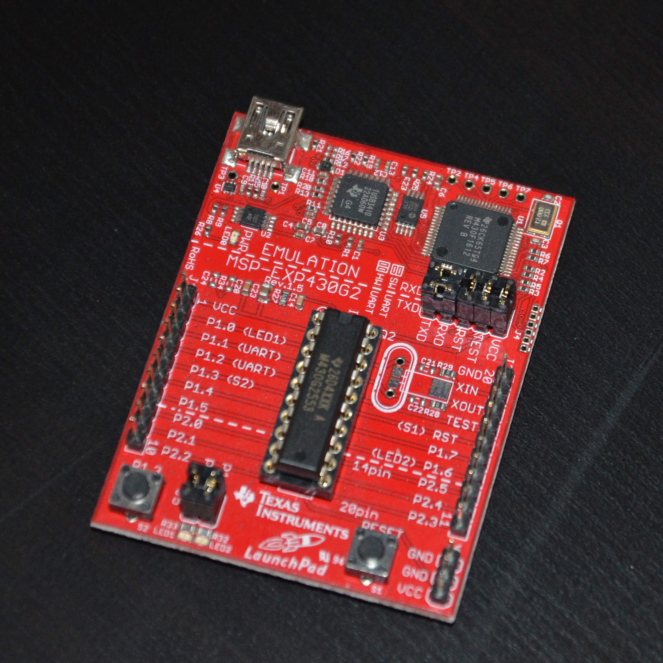
Since UART is relatively slow, it is sometimes implemented bit-banged using standard GPIOs rather than with the USCI peripheral as we have. On the Launchpad, TI has given us the option to use either software UART (bit-banging) or the hardware UART (USCI) with some jumper settings on the board. They made some changes between rev 1.4 and 1.5 to facility this functionality, so the jumper settings between the two are different. If your board is older than rev 1.4, I suspect it will be the same, but if not please inform me.
In both cases, the board is shipped with the jumpers set for software UART, therefore we have to change them. On the rev 1.4 boards, you will need some jumper cables, since you need to cross the pins like this:
On rev 1.5, they made it a bit easier and you simply need to rotate the two jumpers 90 degrees as follows:
Now your hardware should be ready to go. When you connect your Launchpad to the USB port on your computer, the device will enumerate as two classes: HID (human interface device) required for the programming and debugging, and CDC (communications device class) for the UART. In Windows, if you check in the device manager, you will see that the device is not found. This is normal, and TI supplies drivers for both channels (more on this later). On Linux (running as a host), the CDC channel comes up as /dev/ttyACMx (where x is an integer value) and can be read directly as if it were a regular serial port. However, connect the debugger using mspdebug, and now you lost your serial connection. The way the debugger and serial port were implemented on the Launchpad is somewhat flawed. What they tried to do is valid, but for some reason it is unfortunately quite flakey, especially in Linux. Only one can run at a time, which is a bit inconvenient, but what’s worse the CDC channel doesn’t work at all in VirtualBox. I tried for days recompiling kernel modules, different setups etc… with no luck. There are few options/workarounds which worked for me and you can decide which is best for you.
Option 1: Running in a VM with Windows host using Tera Term in Windows for serial
If you have been following these tutorials from the beginning, you may have set up your environment as I have, a Windows host and Linux guest running in VirtualBox. Unfortunately, the workaround for this setup is the most clumsy of the options. I’m also not the biggest fan because I prefer minicom (and Linux) over Tera Term, but it is fairly reliable nonetheless. The other thing I don’t like about this option is that you have to install drivers on Windows. I will show you how to do it as cleanly as possible.
- Download the MSPWare package from TI’s website.Don’t donwload all of CCS, just MSPWare. I was going to make the drivers easily accessible, but its under export control so unfortunately that wasn’t an option. Install the package. It should create a new directory under your C drive called ‘ti’.
- Now open the device manager in Windows, and look for MSP430 Application UART. It should be under ‘Other Devices’ since Windows can’t find the driver
- Right click and select ‘Update Driver Software’, and in the prompt following, select ‘Browse my computer for driver software’
- In the textbox on the next page, type in C:timspMSPWare_2_00_00_41examplesboardsMSP-EXP430G2MSP-EXP430G2 Software ExamplesDrivers and click next
- Once the driver is installed, it should appear under the ‘Ports’ section, and should be assigned a COM port (mine is COM4 for example)
- Download and install Tera Term
- Open Tera Term and under the ‘Setup’ menu select ‘Serial’
- Set the COM port to match what showed in the Device Manager
- Set the baud rate to 9600
- Set data to 8 bit
- Set parity to none
- Set stop bits to 1
- Set flow control to none
- Save this setup as default by selecting ‘Save Setup’ under the ‘Setup’ menu
You should now have serial access and see the menu print out in Tera Term. If you do not see it, reset the device using S1 or press enter a few times. Now heres the trick to this method. When you attach the Launchpad to VirtualBox, you will lose access to the serial port, so close Tera Term first. Now in Linux, program debug etc.. as usual. If you want to go back to serial, make sure mspdebug is closed, and unplug the Launchpad from the USB port. Wait a few seconds, plug it back in and open Tera Term. You should have serial access again.
Option 2: Linux host environment
If you are following along with a Linux host, minicom is my serial terminal of choice. Minicom is all command line, so if you are not comfortable with that, then you can install putty from the repositories. If you choose to use minicom and are having problems setting it up, I can answer any questions you may have. Once you have your terminal installed, you can plug in the Launchpad and open up /dev/ttyACM0 (or whatever port yours came up as). You should see the serial output being printed at this time. Now if you want to use the debugger, close minicom and open mspdebug. You should be able to program and debug. If you want to go back to serial, you must close minicom, unplug the device, wait a few seconds and plug it back in again before opening minicom.
Option 3: Use an external UART to USB converter
The pitfall with both of the previous options is that you cannot use mspdebug and access the menu at the same time, making debugging difficult. This may not be an issue for now since the code provided should work without modification, however it is ideal to have this capability. To achieve this, you can use a UART to USB converter (this one from Sparkfun is cheap and easy to use) or serial to USB converter with the MAX3232 (the 3.3V compatible version of the MAX232 – see the bread boarded picture from above). With a UART to USB, you can simply remove the jumpers from the Launchpad for the TX and RX lines, and connect the device straight onto the headers using some jumper cables.
Testing the UART
Now that you have your device and PC all set up for UART, reset the device and take a look at the menu. We have only one option for now (we will add to this in the future), which will set the frequency of the blinking LED. Select this option and enter a frequency of 2Hz. From the code described earlier, we know that this only sets a variable containing the timer period. For it to take effect, you must use the push button to start the blinking. Now select the menu option again and change the frequency to 4Hz. Stop and restart the blinking. You should see the LED blink twice as fast. In the next lesson, we will look at improving our UART driver to handle receiving characters even when the CPU is busy doing other stuff.
Chris, I have a simple question here, how would I send integers over UART? Would I have to convert the number from binary to a string, then send that string?
Hey Stephen,
That is a great question. Let me make sure I understand what you are trying to do: by integers you mean binary representation of 16-bit integers? Are the integers sent part of a structure, i.e. do you need to send more than one integer per ‘packet’ so to speak. If you could give me an example of what data you want to transmit, I will be able to be more clear. But that being said, if you are sending integers (16-bit in our case), then you need to break it up into high byte and low byte. So each integer will be sent as two UART transmissions. On the other end, you will have to combine these two back into an integer. For example:
uint16_t data;
uint8_t byte[2] = {(data >> 8) & 0xFF, data & 0xFF};
You are filling the first byte with the MSB, and the second byte with the LSB. On the receiving end you would have to rebuild the integer using the inverse operations.
I’m trying to send ADC data to a PC over UART. There is a buffer for 7 ADC samples. It looks kind of like this:
uint16_t adc_data[7];
I know that I would need to break them down into MSB and LSB.
How do I convert the integers to a string representing the digits in base 10 format?
For example, I have some data from the ADC: 0000-0000-0000-1111. I would want that converted into a string “15”.
I see, I understand your question now. So to convert, you can look at the code I wrote as part of the stopwatch code to display the time. Since your integers are 16 bits, your string would need to have a minimum of 5 characters to support the maximum value. Taking the code from line 145 in src/main.c and making it a bit more generic:
char str[7];
uint16_t val;
int i;
[…]
/* Convert the value to a string */
for (i = 4; (i > 0) && (val > 0); i–) {
str[i] = val % 10 + ‘0’;
val /= 10;
}
Using the same code you can convert each integer into a string. I made str 7 characters in case you want to tack on a new line (‘\n’) to each so its more readable. Also make sure it is null-terminated and pass it to the UART driver, i.e.:
str[5] = ‘\n’;
str[6] = ‘\0’;
uart_puts(str);
hi i want to know how is it possible to connect my mcu to a LORA module using uart
Hi Ralph. If it communicates via UART then you may be able to use the driver (USCI) code and only modify the application code for the protocol of the LORA module. What is the specific LORA module you are looking it?
Hi,
In this tutorial, max232 outputs are connected to msp430 pins. My question is:
MSP430 family pins have a rating of 3.3v whereas MAX232 datasheet says its output is 5v…..so, Will direct connection of both will lead to some damage??
Hi Shivansh,
You are absolutely right. Technically you shouldn’t use the MAX232 because the 5V output is out of spec. You should be using the MAX3232. I use the term “MAX232” to refer to the family of devices that do RS-232 to TTL conversion but it is wrong. Sorry for the confusion! I will edit the tutorial to reflect this.
Thanks!
hi Stephen,
I try to communicate between two micro controller using UART,but i want acknowledgement ,how to implement acknowledgement? in UART please tell me.
Hi,
Its possible to use parity Space or Mark with MSP430?
Hi Mario,
I don’t believe that it is. According to the family reference manual, the register UCAxCTL0 which controls the parity has two fields related to the parity, UCPEN (1 bit) to enable or disable the parity bit, and then UCPAR (also 1 bit) which can be set to either odd or even parity.
hi
how can we pair two Individual links
Hi Amit. What do you mean pair two individual links? What is the use case you are designing for?
Awesome tutorial! I have two peripherals, a serial LCD display and a simple serial radio transceiver. Both are updated infrequently. Would it be possible to share the UART since they will be using different clock speeds? In other words, just reconfigure before each transmit? Or is there a better way to do this?
Thanks, Steve
Thanks Steve! Typically a UART is point to point. If you connect it to 2 devices you will likely have bus contention and even though the settings are invalid for one of the devices, it will try to interpret the signal and get corrupted data. The best option would be to select and MCU with 2 UART peripherals. Otherwise, you could probably use a mux to select which device you are communicating with. You would disable the UART, select a device using a GPIO, setup the UART and then start communicating. Cheers!
Stephen,
Very good article. I’m a top notch HW designer but not as qualified on software and RTOS which I’m trying to improve. I don’t understand why your option 3 says “Option 3: Use an external UART to USB converter”. There is a USB to UART converter on the 430G board, its the emulator, so why not use that, or am I not understanding something here.
I have a msp4305529 and want to understand more how to really communicate through the UART rather than using energia or other libraries. I’m hoping I would apply this article to the 5529 board, which I’ll still try but I don’t see why I need an external USB to UART, this 5529 board has the EZFet lite emulator which can talk to most any msp43x and I’m going to try to use your code to talk to the msp4305529 processor on board although I think I’d have to change something to make the LED flash as they are probably mapped differently from the 430G board.
What I’m trying to get out of this is understand how the UART can control and get status of the msp430 processor I understand communication between the emualor and the target but how do you get bytes that you send to the processor to change registers or write to ports in the MSP430 target or read its status. I would imagine the UART is downloading code to the processor , then tell the processor to execute that code and write status back to the UART to be read by emulator. As i saw you mention you flash the led in this tutorial, that sounded like I could follow this project, then I’ll understand how o use the UART to control the target processor.
But again why cant I just execute you code thru my on board emulator, thats confusing the heck out of me now because I was going to connect the msp4305529 launch pad to my usb port and run this project thru there until I saw your “Option 3” which seems to say I need an external USB to UART converter but the 5529 and the 430G board both have one. Sorry for long winded email, well at least you know people are finding value in you great article. Thanks Don
Hi Don. Thanks for the question. You are correct, the board itself has a UART USB emulator. I prefer not to use it because I have had issues with it in the past, especially on Linux. If you have it working with the onboard option than by all mean use that. I just wanted to point out that there are other options. The majority of the tutorial should be relevant to the 5529. There will be clocking and pin muxing differences for sure, but as far as UART is concerned, if you are using the same peripheral they likely function the same way. If you want to chat more about the UART-USB converter ping me at info@simplyembedded.org. Cheers!
Hey!
Thank you for the tutorial!
One question: in many times the serial connection couldn’t be established. one should reset the device several times, try to flash another code and then back with the code containing uart etc… Do you have an idea about how to deal with this bizarre instability of the software uart implementation in the msp430 and howto add robustness to it.
Thanks in advance
Hi Rag. Thank you! Its hard to say exactly why you are having stability issues. I have not experienced this kind of behaviour. I wonder if your device is somehow faulty. Have you tried another MSP430? Have you tried to connect with the debugger and see what is going on? It could be many things but if you still need help with this get in touch with me by email or the feedback form. Cheers!
Hi Chris,
I want to use the minicom to implement the UART example of your tutorial program, but did not get through it. I have installed the minicom and plug in the Lanuchpad but the minicom is still on initialization… My question is how to open up /dev/ttyACMO or how I can check which port I have to setup?
By the way, I am working on the window 10.
Thanks,
WR
Hello. That was an excellent tutorial!
Can I program MSP430 family microcontrollers with USB/TTL converter? (CP2012 or FTDI) by hooking up Rx/Tx pins to microcontroller. (without launchpad)
Thanks Navadeep! It depends on which device. Some MSP430 devices have a bootloader embedded in ROM which would allow you to do that. Look for the devices which say they support BSL. Have a look at this link for more info: https://www.ti.com/tool/MSPBSL