After much anticipation, we have finally got to the topic that I keep on mentioning, but never explain – interrupts! Interrupts are probably the single most important concept that make every electronic device work as it does. If interrupts didn’t exist, your electronic devices wouldn’t be as responsive, fast and efficient as they are. They are the source for all types of timers and ticks and integrated into most peripherals. Every CPU has interrupt capabilities, although the capabilities vary widely. Interrupts are sometimes neglected because its ‘easier’ to poll than implement interrupts but its generally considered poor design. So what are interrupts? They are really just a way for the hardware to signal the software that some event has occurred. Each event has an entry in what is called the interrupt vector table – a table of pointers to functions stored in memory (either flash or RAM), which the CPU will jump to automatically when the interrupt fires. These functions are called interrupt service routines (ISR), and though some may be included as part of the compiler libraries, most need to be implemented by the programmer. Interrupt service routines must be as quick and efficient as possible, so as to not stall the software which was executing. They must also be efficient with the stack. In operating system environments, interrupt handlers may operate on a separate [software] stack which is much smaller than a typical process or thread stack. Also, no blocking calls should be made. Taking too long in the ISR can result in lost data or events. Interrupts have attributes that may or may be programmable, depending on the architecture and the device. In this lesson, we will learn about the different types of interrupts, their attributes, how to implement them, what happens when an interrupt fires, and how they are used in real world applications. The generic interrupt vector table is available in table 2-1 of the family reference manual, while device specific vectors are defined in table 5 of the datasheet.
Enabling and disabling interrupts
Most interrupts can be enabled or disabled by software. Typically there is a register that will perform the function globally for all interrupts or groups of interrupts, and then additional registers for individual interrupts. Disabling an interrupt is often referred to as ‘masking’ the interrupt. Interrupts are almost always accompanied by a status or flag register which the software can read to determine if a specific interrupt has fired. This is required because sometimes many physical interrupts are connected to the same interrupt request (IRQ) – the signal to the CPU. The flag is required because the interrupt line may only be active for a very short amount of time and the software may not respond fast enough. The flag ensures the the state of the interrupt is stored somewhere until it is read and cleared by the software. It is also often used to acknowledge and clear the interrupt, as is the case with the MSP430. Enabling and disabling interrupts in the MSP430 at a global level is done through the status register. We have not looked in detail at the contents of the status register, so lets do that now.

- V: overflow bit
- Set when the result of an arithmetic operation overflows the signed-variable range
- SCG1: system clock generator 1 (SMCLK) enable / disable
- 0 – SMCLK is on
- 1 – SMCLK is off
- SCG0: system clock generator 0 (DCOCLK) enable / disable
- 0 – DCO generator enabled
- 1 – DCO generator disabled is DCOCLK is not the used for MCLK or SMCLK
- OSCOFF: enable / disable LFXT1 crystal oscillator
- 0 – enable LFXT1 crystal oscillator
- 1 – disable LFXT1 crystal oscillator when LFXT1CLK is not used for MCLK or SMCLK.
- CPUOFF: Turn the CPU on or off
- o – CPU on
- 1 – CPU off
- GIE: General interrupt enable
- 0 – disable interrupts globally (NMIs not included)
- 1 – enable interrupts globally (note: interrupts still need to be enabled individually by their respective interrupt enable register)
- N: negative bit
- 0 – when result of an operation is positive
- 1 – when the result of an operation is negative
- Z: zero bit
- 0 – when the result of an operation is non-zero
- 1 – when the result of an operation is zero
- C: carry bit
- 0 – when the result of an operation does not contain a carry bit
- 1 – when the result of an operation produes a carry bit
As mentioned above, GIE is the field used to enable or disable maskable interrupts on the device. The compiler provides intrinsic functions to do this in C, __enable_interrupts and __disable_interrupts. Maskable interrupts are disabled by default on reset, so the software must enable them to use them. Not all interrupts can be disabled. These are called non-maskable interrupts, or NMI. There are usually some interrupts on a device that are reserved as NMIs. NMIs are typically critical errors to which the software must respond and handle in order to continue execution. The MSP430 has three NMIs.
- Oscillator fault: the clock module has detected a fault in the oscillator
- Flash memory access violation: the flash memory was accessed while busy
- NMI: the reset pin on the device can be configured to NMI mode and when it becomes active it will source this interrupt
Sometimes these types of interrupts are referred to as exceptions. Exceptions can also be raised due to some non-recoverable fault. It is a similar concept to a software exception, but implemented in hardware. On the MSP430, there is one non-recoverable exception, the illegal instruction fetch, which causes a reset. On some architectures, this exception can be handled and the handler may increment the program counter to the next address to try and skip over it. Other examples of exceptions which exist on other architectures are the divide by zero and invalid memory access. Although not documented as an exception, the MSP430 does source the reset vector if attempting to execute from an invalid memory space such as an address not in RAM or flash.
Edge vs level based, active high / active low
One very common use for interrupts is to detect changes in GPIO inputs. Stemming from our push button code which has to poll the P1IN register, enabling an interrupt on a GPIO would allow the hardware to signal the software when the input has changed values. Not all GPIOs are interrupt capable, so remember to check in the device datasheet when choosing which pin to connect it to. GPIO interrupts have their own subset of properties. The first property is the active signal level – either active high or active low. Active high means that the signal is interpreted as active when the line is high (a positive voltage), while active low means the signal is interpreted as active when the line is low (0V or ground). However, the second property, edge vs level based (also known as edge or level triggered interrupts), defines when the interrupt actually fires. Edge based interrupts will only fire once as the state of the line transitions from the inactive level to the active level. Level based interrupts will fire continuously while the input is at the active level. In order to handle a level based interrupt, the ISR should mask it so that it does not fire continuously and effectively stall the CPU. Once the source of the interrupt is cleared, the interrupt may be enabled so it can fire again. Level based interrupts are sometimes used to perform handshaking between the source of the interrupt and the software handling it. The software would enter the ISR, check the status of the source of the interrupt to determine exactly what caused the interrupt (remember multiple sources per IRQ), and then clear source condition and the flag. If the interrupt condition is successfully cleared, the line will return to the inactive state and the software will continue on. Otherwise, the line will remain active and the interrupt would fire again. The MSP430 only supports edge based interrupts.
Interrupt priorities
Another important attribute of interrupts is the priority. Interrupt priorities determine which interrupt service routine will be called first if two interrupts fire at the same time. Depending on the interrupt controller, some interrupt priorities may be configurable by software. The MSP430 does not support this, all interrupts have a fixed priority. The interrupt priorities on the MSP430 are in descending order from highest address in the vector table to the lowest. One important concept related to interrupt priorities is interrupt nesting. If one interrupt fires and the ISR is invoked, and while in the ISR another interrupt of a high priority fires, the executing ISR may be interrupted by the higher priority one. Once the higher priority ISR has completed, the lower priority ISR is then allowed to complete. In the case of the MSP430, nesting is not dependant on the priority. Any priority interrupt will be serviced immediately if nested interrupts are enabled. Nesting interrupts is an advanced topic an will not be enabled for this tutorial. If an interrupt fires while an ISR is executing, it will be serviced only once the ISR is complete.
Reset vector
The reset vector is the single most important interrupt available. Without it, code would never begin executing. The compiler [typically] automatically populates the reset vector with the address of the entry point of the .text section, i.e. the __start function. When a device is powered on or the reset pin is toggled, the reset vector is sourced and the CPU jumps to the address it contains. Going back to the linker script from last lesson, the table of memory regions has a region defined for each interrupt vector. A region called RESETVEC is located at 0xFFFE, defined with a size of 2 bytes. Then a section called __reset_vector is created and assigned to this memory location. The data allocated to this section will be the address of the reset vector ISR. To show that the reset vector is assigned the start-up code, the following command can be used:
/opt/msp430-toolchain/bin/msp430-objdump -D a.out | less
Passing the argument -D to objdump is similar to -S, but it dumps the disassembly for all sections rather than just the .text section as -S does. This is required because as mentioned above, the reset vector is part of its own section, not the .text. The output of this command will look like this:
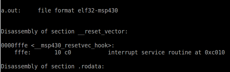
The first couple lines of code are all we are interested in. We can see that the first section in the output is the reset vector. In it there is only one label: ‘__msp430_resetvec_hook’. At this label there is 2 bytes of data allocated with the value of 0xc010 (keep in mind the endianess). Search for 0xc010, and you will see that this is the address of __start, the entry point. Therefore as expected, when sourced the reset vector shall cause the CPU to jump to the start-up code.
The watchdog timer
The watchdog is another very important interrupt. It is actually a whole module which is implemented as part of almost every MCU, SoC, etc… The purpose of the watchdog is to ensure that the software is running and had not stopped, crashed or otherwise been suspended. It is very rare that you find an embedded system without a watchdog. If implemented correctly in both hardware and software, the device should never stall indefinitely. Once enabling the watchdog, the software must pet it periodically with an interval less than its timeout. Failure to do so will result in the watchdog resetting the device. In the case of the MSP430, the watchdog interrupt is the same as the reset vector, so a watchdog interrupt will reset the device. Some devices have more complex watchdogs which generate an intermediate interrupt to allow the software to perform any logging or cleanup operations before resetting. The MSP430 watchdog module does not support this, but it has an additional interesting feature – it can be configured as a regular 16-bit timer. This could be useful if an additional timer if needed. We will be configuring the watchdog in watchdog mode because it is important to understand how to setup the module and how it should be maintained by the software. The watchdog is configured and monitored through the 16-bit register WDTCTL and two additional registers, interrupt enable 1 (IE1) and interrupt flag 1 (IFG1).

The field of these registers are defined as follows:
- WDTPW: watchdog password. A password is required in order to modify any of the watchdog configuration. This is to ensure that the change is actually desired and not a result of some rogue code or bad pointer. The password to access the register is 0x5A
- WDTHOLD: watchdog hold
- 0 – enable watchdog timer
- 1 – hold the watchdog timer
- WDTNMI: reset pin function select
- 0 – reset function
- 1 – NMI function
- WDTTMSEL: configure the mode of the watchdog
- 0 – watchdog mode
- 1 – interval timer mode
- WDTCNTCL: counter clear. Used by software to pet the watchdog
- 0 – no action
- 1 – clear counter
- WDTSSEL: watchdog clock source select. The watchdog clock can be sourced from either the SMCLK or the ACLK
- 0 – SMCLK
- 1 – ACLK
- WDTISx: watchdog interval select. Used to select the timeout of the watchdog
- 00 – 32768 clock cycles
- 01 – 8192 clock cycles
- 10 – 512 clock cycles
- 11 – 64 clcok cycles
- NMIIE: NMI interrupt enable
- 0 – NMI interrupt disabled
- 1 – NMI interrupt enabled
- WDTIE: watchdog interrupt enable only used in interval timer mode
- 0 – not enabled
- 1 – enabled
- NMIIFG: NMI interrupt flag
- 0 – no interrupt pending
- 1 – interrupt pending
- WDTIFG: watchdog interrupt flag, cleared by software and can be used to determine if a reset was caused by a watchdog
- 0 – no interrupt pending
- 1 – interrupt pending – watchdog timer expired
The blank fields of IE1 and IFG1 registers are determined by the specific device and will be covered as needed. Now lets use what we have learned to disable and enable the watchdog timer in our existing code and watch the device reset. Below is a set of a set of functions to perform these actions.
static void _watchdog_disable(void)
{
    /* Hold the watchdog */
    WDTCTL = WDTPW + WDTHOLD;
}

static void _watchdog_enable(void)
{
    /* Read the watchdog interrupt flag */
    if (IFG1 & WDTIFG) {
        /* Clear if set */
        IFG1 &= ~WDTIFG;
    }

    _watchdog_pet();
}

static void _watchdog_pet(void)
{
    /**
     * Enable the watchdog with following settings
     * - sourced by ACLK
     * - interval = 32768 / 12000 = 2.73s
     */
    WDTCTL = WDTPW + WDTCNTCL;
}
The first function disables the watchdog exactly as we do currently in our main function. The _disable_watchdog function should be called right at the beginning of your code in order to avoid accidentally generating a reset when modifying the configuration. You can go ahead and replace the existing watchdog code in main with a call to this function. In the enable function, the watchdog timer interrupt flag is read and cleared if required. If the flag is set, some action could be performed such as logging the number of watchdog resets but we have no need at this time. Then _watchdog_pet is called. Petting the watchdog will effectively enable it as well. Only two fields are set in the WDTCTL register, the password field WTDPW and the clear counter bit WDTCNTCL. The watchdog will be enabled since the WDTHOLD bit is cleared. The timeout of the watchdog timer is determined by the clock source select bit WDTSSEL and the interval select field WDTISx. This means the watchdog timer will source its clock from ACLK and expire after 32768 clock cycles. In lesson 4 we did not configure ACLK but now we must. ACLK should be configured to be sourced from VLOCLK, which is approximately 12kHz. If we tried to source it from MCLK or SMCLK, the timeout would be too short for the delay required by the blinking LED. To configure ACLK, in main we must add a new line under the clock configuration.
/* Configure the clock module - MCLK = 1MHz */
DCOCTL = 0;
BCSCTL1 = CALBC1_1MHZ;
DCOCTL = CALDCO_1MHZ;

/* Configure ACLK to to be sourced from VLO = ~12KHz */
BCSCTL3 |= LFXT1S_2;
Since the interval selector is set to 32768 clock cycles at 12kHz, the timeout of the watchdog will be 2.73s. Therefore the watchdog must be pet at least every 2.73s. Since our loop delay 500ms each iteration, we are within the requirements of the watchdog. Now lets see that the watchdog actually fires and resets the device. Call the watchdog enable function right after detecting the button press.
/* Wait forever until the button is pressed */
while (P1IN & 0x08);

_watchdog_enable();
Typically you would want to enable the watchdog as soon as possible, especially before any infinite loops. In case this I want you to control when the watchdog is enabled so that you can see when it resets. Compile the code and program it to the device. Set a breakpoint at the new function _watchdog_enable (use nm to find the address). Run the code and press the button. When it stops at the breakpoint run it and press the button again. The breakpoint will be hit again. This shows that the device is restarting. To verify that it is because of the watchdog, we can read the register IFG1 and see if WDTIFG is set. IFG1 is located at address 0x02 as indicated in both the datasheet and the family reference manual. Read this address using the md command. You should see the following:
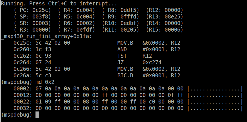
The value of the IE1 is 0x7, therefore the WDTIFG bit is set. It is important to note that the other bits which are set are defined by the device specific implementation which can be found in the datasheet. They are PORIFG (bit 2), the power on reset interrupt flag, and OFIFG (bit 1), the oscillator fault interrupt flag. These two bits are set because that is their default value after reset. Now we will pet the watchdog to prevent it from resetting the device. Call _watchdog_pet inside the while loop that toggles the LED.
while (1) {
    _watchdog_pet();

    /* Wait for LED_DELAY_CYCLES cycles */
    __delay_cycles(LED_DELAY_CYCLES);

    /* Toggle P1.0 output */
    P1OUT ^= 0x01;
}
Compile the code and program the board. Press the button to enable the watchdog and notice that now the board does not reset (note the address of the breakpoint will need to be adjusted since you added new code). And that’s basically how to pet a watchdog. As we add more code to our project, we will see how the watchdog needs to be managed to ensure that it only trips if there is a failure and not because the code is waiting for some input.
Interrupt handling on the MSP430
Now we will get into the details of interrupt handling on the MSP430. When an interrupt fires, a few things have to happen before entering the ISR:
- The instruction that is currently being executed must complete
- The PC (program counter) is pushed onto the stack
- The SR (status register) is pushed onto the stack
- The highest priority interrupt pending is selected
- The interrupt source flag is set
- The SR is clear (which disables interrupts)
- The address in the interrupt vector is loaded into the PC
Now the CPU can begin executing the ISR. All of this happens in hardware, no software is involved so you will never see this in code. It can be inspected by using the debugger however, and we will see this shortly. The time starting from when the interrupt is triggered to the time when the ISR is invoked, is called the interrupt latency. In the case of the MSP430, the interrupt latency is 6 clock cycles.
The ISR has some responsibilities of its own before executing the application code. If written in C, this is taken care of by the compiler. In assembly it must be implemented manually. To see how this works, we are going to create an interrupt service routine in C to detect the button press. Unfortunately, there is no way defined by the C programming language on how to declare an interrupt handler, it is left up to the compiler. Therefore what you will learn is only applicable for gcc and may look slightly different on other compilers. To declare an ISR in gcc you must use the ‘attributes’ feature. Attributes provide additional functionality which are non-standard. When possible, using attributes should be avoided so that the code is compiler agnostic (read – portable from one compiler to another). There are some attributes which are common across compilers and it is often considered good practice to define them as macros in a separate header file (often name compiler.h) which uses hash defines to compile the macros relevant for that compiler. To declare the interrupt service routine, we first need to figure out which interrupt we are going to write an ISR for. On the MSP430, each IO port is assigned an interrupt. It is up to the software to determine which pin on the port was the source. So how so do we refer to this interrupt? Open the msp430g2553.h header file and search for ‘PORT1_VECTOR’. You will find the list of interrupt vectors for this device. The desired vector should be passed to the interrupt attribute. It tells the compiler in which section to place the address of your ISR. Therefore, our empty function declaration would look like this:
__attribute__((interrupt(PORT1_VECTOR))) void port1_isr(void) {;}
ISRs must have a return type of void and have no arguments. Lets see what has been generated using the the objdump command from earlier to disassemble the code.
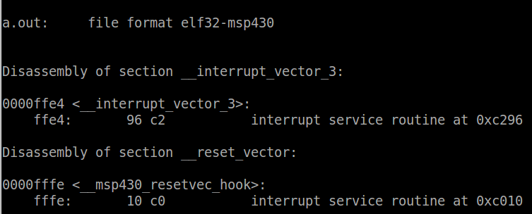
We can see that a new section has been added called __interrupt_vector_3. To understand this we need to go to the datasheet and find the address of the interrupt vector for port 1 (since our button is connected to P1.3). The vector is located at address 0xFFE4. In the linker script memory region table, this address is part of the region VECT3. In the sections table, we can see that the section __interrupt_vector_3 is loaded into region VECT3. This means that when passing vector 3 (which PORT1_VECTOR is defined as) to the interrupt attribute, the compiler will place the address of that function at 0xFFE4. From the objdump output, we can see the value at 0xFFE4 is 0xC278. Search in the rest of the file for this address and you will find that it is in fact our function port1_isr. Currently the function is empty, so lets go back and fill it in. In order to start or stop the the blinking LED using the push button, we will need some sort of signal between our main function and the ISR. We will use a simple variable which will be toggled by the ISR.
static volatile int _blink_enable = 0;
For some of you volatile may be a new keyword that you have not used before. Volatile tells the compiler that the value of that variable may be changed at any time, without any nearby code changing it. This is the case for an ISR. The compiler cannot know when the ISR is going to fire, so every time the variable is accessed, it absolutely must read the value from memory. This is required because compilers are smart, and if they determine that nothing nearby can change the value, it may optimize the code in such a way that the value will not be read. In this case, that change will occur in the ISR so it must be read every single time. Next we have to introduce a few new registers, PxIES, PxIE and PxIFG (where ‘x’ is the port number). All three of these register follow the same bit-to-pin convention as the other port configuration registers we have previously discussed. The latter two are similar to IE1 and IE2, they are the port interrupt enable and port interrupt flag registers. PxIES is the interrupt edge select registers where a bit set to 0 signals an interrupt for a low-to-high transition (active-high) and a bit set to 1 signals an interrupt on a high-to-low transition (active-low). Now that we have covered how to configure the interrupts, let’s modify our code to use it. First, instead of waiting in a while loop to start the LED blinking, let the interrupt handler enable it, so remove the first while loop. The interrupt should be configured before the watchdog is enabled. Since the button is on P1.3 and it is pulled-up, we want to set the interrupt to occur on a high-to-low transition so bit 3 in PIES and P1IE should be set high. Finally, enable interrupts using the intrinsic function __enable_interrupt. In the while loop, modify the code to only blink the LED when _blink_enable is non-zero. Your code should look something like this:
/* Set P1.3 interrupt to active-low edge */
P1IES |= 0x08;

/* Enable interrupt on P1.3 */
P1IE |= 0x08;

/* Global interrupt enable */
__enable_interrupt();

_watchdog_enable();

/* Now start blinking */
while (1) {
    _watchdog_pet();
    if (_blink_enable != 0) {
        /* Wait for LED_DELAY_CYCLES cycles */
        __delay_cycles(LED_DELAY_CYCLES);

        /* Toggle P1.0 output */
        P1OUT ^= 0x01;
    }
}
Now for the ISR. Since one interrupt is sourced for all the pins on the port, the ISR should check that P1.3 was really the source of the interrupt. To do so, we must read bit 3 of P1IFG and it is high, toggle _blink_enable and then return.
__attribute__((interrupt(PORT1_VECTOR))) void port1_isr(void)
{
    if (P1IFG & 0x8) {
        /* Clear the interrupt flag */
        P1IFG &= ~0x8;

        /* Toggle the blink enable */
        _blink_enable ^= 1;
    }
}
All of these changes are available in the latest lesson_6 tag on github. Recompile the code and use objdump to inspect the ISR. The address of the ISR can be found by looking at the contents of the __interrupt_vector_3 section from objdump as we did for the reset vector.
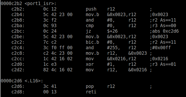
The first operation is to push R12 onto the stack. R12 is the register the compiler is going to use to toggle the variable _blink_enable. It must ensure that the previous value is stored because it may be used by the function which has been interrupted. If the ISR clobbers the register value, when the interrupted function continues execution, the register would have the wrong value. This applies to all registers and it is up to the compiler to determine which registers are used by the ISR and thus must be pushed on the stack. In this case only R12 is being used, so the most efficient implementation is to push only R12. Now that R12 is free to use, it can be used to check the value of P1IFG and ensure the flag is set. Then in order to acknowledge the interrupt so it doesn’t fire again, the flag must be cleared. The address of P1IFG (0x23) is loaded into R12 and bit 3 is cleared. Finally the address of our variable _blink_enable is loaded into the register and the value is XOR’d with 0x1. The stack is popped back into R12 to restore the initial value before returning. To return from an interrupt, the RETI pseudo-instruction is used. RETI, which stands from return from interrupt, tells the CPU to pop off the SR and PC values back into their respective registers. Now that all the registers are exactly as they were before the interrupt fired, the flow of execution continues on as if nothing happened. Now program the device and run the new code. The LED will begin blinking once the button is pressed, and pressing the button again will toggle the blinking on or off. Set a breakpoint at port1_isr. When the button is pressed the CPU will be stopped at the ISR. The stack pointer is set to ~0x3f4 (depending where exactly the code was interrupted) and dumping the memory at this location, we can see the result of entering the ISR.
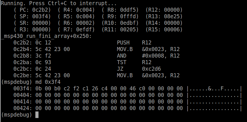
The first 2 bytes on the stack will be the SR. The value of the status register stored in the stack will be different from that currently dumped by mspdebug since it is cleared by the hardware. The next 2 bytes will be the PC, in this case 0xc2b0. Using objdump to view the code at this address, we can see that the CPU was interrupted right at the end of _watchdog_pet, which is called within the while loop, as expected. Your values may differ slightly depending where exactly the PC was when you pressed the button. What we really have experienced here is something commonly known as a context switch. It is the foundation of all software, not just embedded systems. Almost every operating system uses context switching to some extent, usually triggered by an interval timer firing an interrupt periodically. This is what allows you have to many threads and processes running on just one CPU. Its the illusion of parallel operation through the use of extremely fast context changes many times per second. The definition of the context is dependent on the architecture. In the case of the MSP430, it is all the main CPU registers we have discussed in the last lesson. When the ISR fires, we have to save all of these registers that could be modified so when the interrupt completes, the context can be restored. A context switch of a thread or task (synonymous terms) would have to save all the registers on its stack before restoring the registers for the task about to run. There is some really interesting stuff here, and this is only an introduction. We will not be creating a multi-threaded system since that is way beyond the scope of this course, but interrupts are a form of context switch so it is important to understand how powerful and important they really are in embedded systems.
First, let me thank you very much for the helpful tutorials! They are great and there’s nothing else out there with this level of quality and detail.
What is your thought on the newly released Red Hat MSP430 gcc compiler (http://www.ti.com/tool/msp430-gcc-opensource)? I’m trying to set up my environment to use it instead of the mgspgcc compiler since the Red Hat compiler is supposed to be compatible with the TI compiler code syntax..etc For example, it is supposed to be able to support the “#pragma vector=….” directive instead of having to use the “__attribute__((interrupt(PORT1_VECTOR))) void port1_isr(void)” format.
Sorry, I guess you are using the new TI Red Hat gcc compiler. I’m still having trouble getting it to compile when using the “pragma” directive? According to their docs it should be supported by this compiler, or am I wrong?
Thanks.
Hi Mohammed,
Thank you very much I’m glad you find these tutorials helpful. I was not aware that TI made the claim that the Red Hat gcc is expected to support all the same compiler directives as TI’s own compiler. Where did you see this information? I have never successfully used the vector pragma myself using any version of mspgcc. Is your goal to make your code compatible with both compilers?
Chris,
Yes, making it compatible with both compilers was part of my goal. The main reason I tried to get it to work with the new gcc is to be able to reuse their examples as-is.
They don’t explicitly make that claim, however it is kind of inferred. In their wiki post here (http://processors.wiki.ti.com/index.php/Using_MSP430-GCC_with_CCSv6) they have a section titled “Changing an existing CCS project created for TI compiler to use MSP430 GCC”. In that section they make no mention of code changes necessary to make it compile with gcc so I assumed that it the code would compile as-is.
Do you know of any reference material to guide through porting from TI’s compiler-compatible code and GCC?
Thanks,
Mohammad
“
Hi Mohammad,
Sorry for the delayed response. Just got back from vacation! Looks like TI must be missing some information there. Personally have not found much about the TI MSP430 gcc compiler in terms of documentation other than the quick start guide (http://www.ti.com/lit/ml/slau591a/slau591a.pdf). I would try posting on TI’s forums and see if they can give you an accurate answer. Somehow though I doubt they put in the effort to make them completely compatible. I am sure some of the built-in libraries/intrinsics may be reused, but compiler specific constructs would be harder. I will suggest the following workaround that’s pretty industry standard for making compiler independent code. Create a new header file called compiler.h. In it, do something like this:
#ifdef __GNUC__
#define ISR(v) __attribute__((interrupt(v)))
#else
#pragma vector=v
#endif
Include compiler.h in whatever file has your ISR and use the ISR macro to define it. The hash define __GNUC__ is always present for gcc. I am sure there is one also specifically for CSS. As you continue to find incompatibilities between the two compilers, you can simply add to this file. Hopefully this helps.
Hi, love the tutorials so far but I’m a bit confused on Lesson 6. I checked out lesson 6 in git which I believe we’re supposed to do but notice that the code does not match what you have listed in the tutorial. For instance it does not have these two lines;
/* Wait forever until the button is pressed */
while (P1IN & 0x08);
above this line on line 106;
_watchdog_enable();
I added them and compiled the code, making no other changes, yet when I press the button the code runs yet the light doesn’t blink. Furthermore when I use the md 0x2 command to view the memory it shows the value of IE1 to be 0xe not 0x7 as listed. Finally, when I run it the second time and press the button the light flashes and continues to but the code never stops at the breakpoint a second time. Thanks for any help.
Hi Erik. Took me a while to figure out that discrepancy but I now I remember why that is. Those two lines of code you mention which are not in the repository, they were just for demonstration purposes – so it is good they were not checked in. What I wanted to show is that once you press the button and enable the watchdog, if you do not pet it (as per the while loop from lesson 5), the watchdog will reset the board after ~2 seconds. Sorry if that wasn’t clear. It was just meant to be an example to demonstrate that the watchdog does in fact work. You don’t really want the watchdog tripping in practice 🙂 If you see the watchdog trip, take the code from lesson 5 and just apply the changes from lesson 6 up till that point.
Great Tutorials !
“From the objdump output, we can see the value at 0xFFE4 is 0xC278.”, it looks like you made a little typo here.
Hi Chris,
what is #pragma vector=PORT1_VECTOR?
How it works in MSP430
Hi Darshan. Pragmas are just a way of notifying the compiler of some specific attribute. In this case, it is telling the compiler that the function is an interrupt handler. The compiler will then place the function in the interrupt vector table at the location for the specified vector. Cheers.