In the last lesson, we created a very simple UART driver which polls the peripheral for received data. As we learned with the push button back in lesson 6, this is not the optimal solution for most drivers. Once we start adding in more functionality to the main loop, it is possible that characters may be missed because the CPU is busy doing other things. We can easily simulate this scenario by adding a big delay into the the main loop – say one second – by using the __delay_cyles function.
watchdog_pet();
menu_run();
__delay_cycles(1000000);
The menu_run function reads the UART input and is then delayed one second before checking for the next character. This delay is exaggerated but it demonstrates an important point. Compile the code with this delay and then run it. Try typing ‘1234’ quickly at the menu prompt. You will notice that characters are dropped, only one or two of the characters are echoed back. What happens here is each character received by the peripheral is placed into the UCA0RXBUF register. If the software does not read the data out of the register before the next character is received, the value in the register will be overwritten.
The solution is twofold: detect incoming data using interrupts rather than polling and then store each received character in a first-in-first out (FIFO) buffer. A FIFO is a type of buffer (or queue) in which the data enters and exits in the same the order. If the FIFO is full and there is another piece of data to enter, it is either dropped (the newest data is lost) or the oldest data in the FIFO is pushed out and discarded. There are different types of FIFOs so I won’t cover all the possible designs, but we will look at one in detail shortly. Using a FIFO to queue received data is very common. In fact, the UCA0RXBUF register can be considered a FIFO of depth 1 (depth of ‘n’ means ‘n’ elements fits in the FIFO) which drops the oldest data once full. The UCA0STAT[UCOE] field will be set if this condition, called an overrun error, occurs.
Some higher end MCUs provide a UART FIFO in hardware. However, even with hardware queuing, it may be optimal to implement a software queue in conjunction to provide more flexibility. In this tutorial we will implement on type FIFO which can be used for queuing all types of data.
Ring buffer basics
The type of FIFO we will be implementing is called a ring buffer, also known as a circular buffer. It is called a ring buffer because data can wrap around back to the beginning, provided there is space. Really it is just implemented as an array but the beginning of the queue does not have to start at the first element of the array, and the end does not necessarily end at the last element in the array. The start of the queue could begin somewhere in the middle of the array, wrap around the last element back to the beginning and end there. The start of the queue is where new data will be written to. The end of the queue contains the oldest data and is where the caller will read from. These are commonly referred to the head and tail respectively. Note these are just naming conventions for the sake of theory – their exact meaning is implementation specific as you will see later.
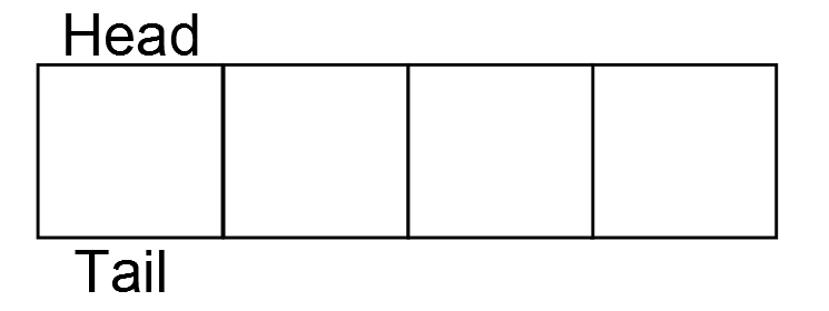
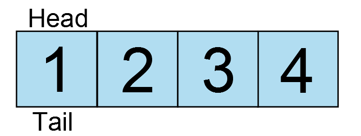
To help clarify this how the ring buffer works, lets take a look at some diagrams. Let’s say our ring buffer can hold 4 elements. When it is initialized, the head and tail are both at the first element.
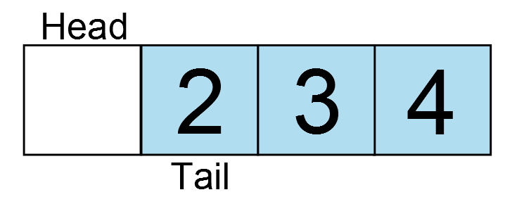
There is no data in the ring buffer. In the next image, one element is added as indicated by the light blue box.
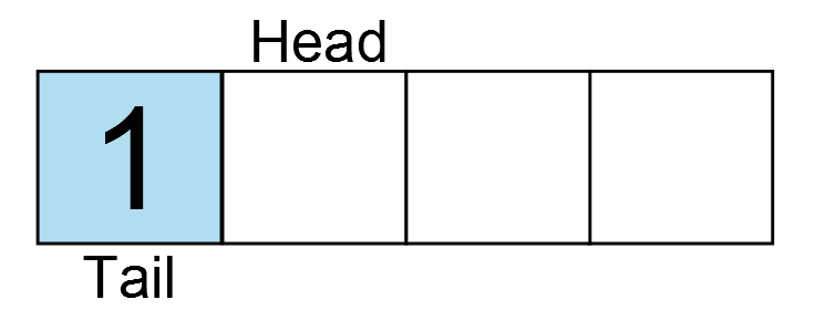
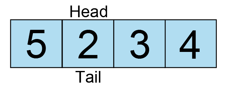
Data is inserted at the current head, and the head is incremented to the next element. Another key is pressed, and another character is entered.
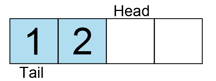
And another…
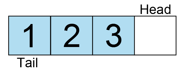
And another…
And another… oh wait, the ring buffer is full! The head has wrapped around back to the position of the tail. If one more write occurs, the oldest data would be lost. Therefore, the next write would fail. So what if the application now reads a character from the ring buffer?
The tail increments and there is one free element in the ring buffer. Now one more character is added and fills the buffer again, but now the ring wraps around the array.
And around and around the data goes. But there is a catch. Do you see a potential implementation challenge with these diagrams? The head and tail are on the same element in two instances: when the buffer is empty and when the buffer is full. So how can you differentiate between the two? There are several ways to handle this issue. A common implementation to determine if the ring buffer is full is to keep track of the count of data. This means for every write the counter is incremented and for every read the counter is decremented. It is very easy to implement, however this approach has one major flaw. The write will be invoked from an interrupt and the read will be invoked from the application. Having a single variable to track the count would mean we MUST have a critical section in both functions. Going back to the lesson on timers, we learned that a critical section is necessary when a variable is accessed by more than one context. This means that while reading data out of the ring buffer, interrupts would have to be temporarily disabled. Although sometimes unavoidable, it is best to try and write code that will not require the use of critical sections. In the following section we will implement a ring buffer which addresses both of these concerns.
Implementing a lock-free ring buffer
Our implementation of the ring buffer will be generic enough so that we can use it for any type of data, not just characters. This means we have to know not only the number of elements in the ring buffer, but also the size of the elements. To start, let’s take a look at the rb_attr_t structure in the header file include/ring_buffer.h.
typedef struct {
    size_t s_elem;
    size_t n_elem;
    void *buffer;
} rb_attr_t;
This structure contains the user defined attributes of the ring buffer which will be passed into the initialization routine. The structure contains the member variables s_elem – the size of each element, n_elem – the number of elements and buffer – a pointer to the buffer which will hold the data. The design of this structure means that the user must provide the memory used by the ring buffer to store the data. This is required because we don’t have memory allocation functions readily available. Even if we did, it is commonly considered bad practice to use dynamic memory allocation in embedded systems (i.e. malloc, realloc, calloc, etc…).
In the header file, there is typedef of the ring buffer descriptor rbd_t.
typedef unsigned int rbd_t;
This descriptor will be used by the caller to access the ring buffer which it has initialized. Its is an unsigned integer type because it will be used as an index into an array of the internal ring buffer structure located in src/ring_buffer.c. Apart from the attributes we discussed in the previous paragraph, the head and tail are all that is required for this structure. Notice how the head and tail are both declared as volatile. This is because they will be accessed from both the application context and the interrupt context.
struct ring_buffer
{
    size_t s_elem;
    size_t n_elem;
    uint8_t *buf;
    volatile size_t head;
    volatile size_t tail;
};
This structure is allocated as an array private to this file. The maximum number of ring buffers available in the system is determined at compile time by the hash define RING_BUFFER MAX, which for now has a value of 1. The allocation of the ring buffer structure looks like this.
static struct ring_buffer _rb[RING_BUFFER_MAX];
The initialization of the ring buffer is straight forward.
int ring_buffer_init(rbd_t *rbd, rb_attr_t *attr)
{
    static int idx = 0;
    int err = -1;

    if ((idx < RING_BUFFER_MAX) && (rbd != NULL) && (attr != NULL)) {
        if ((attr->buffer != NULL) && (attr->s_elem > 0)) {
            /* Check that the size of the ring buffer is a power of 2 */
            if (((attr->n_elem - 1) & attr->n_elem) == 0) {
                /* Initialize the ring buffer internal variables */
                _rb[idx].head = 0;
                _rb[idx].tail = 0;
                _rb[idx].buf = attr->buffer;
                _rb[idx].s_elem = attr->s_elem;
                _rb[idx].n_elem = attr->n_elem;

                *rbd = idx++;
                err= 0;
            }
        }
    }

    return err;
}
First we check that there is a free ring buffer, and that the rbd and attr pointers are not NULL. The static variable ‘idx’ counts the number of used ring buffers. The second conditional statement verifies that the element size and buffer pointer are both valid. The final check is performed to test that the number of element is an even power of two. Enforcing this will permit us to make optimizations in the code which we will discuss shortly. To verify n_elem is a power of two, there is a trick which takes advantage of the binary number system. Any value which is a power of two will have only one ‘1’ in it’s binary representation. For example:


Note that the 1 is left shifted by the number in the exponent. If one is subtracted from any power of two, the result will be a consecutive series of 1s from bit zero to bit ‘exponent – 1’.


If the the original value is logical AND’ed with this string of ones, the result will always be a zero for a power of two.


If the initial value was not a power of two, the result will always be non-zero.


A similar technique will be used to wrap the head and tail indices which we will look at shortly.
Now that all the arguments are validated, they are copied into the local structure and index is passed back to the caller as the ring buffer descriptor. The variable idx is also incremented to indicate the ring buffer is used. The value will now be RING_BUFFER_MAX so if the initialization function is called again, it will fail.
Before moving on to the rest of the public APIs, lets take a look at the two static helper functions: _ring_buffer_full and _ring_buffer_empty.
static int _ring_buffer_full(struct ring_buffer *rb)
{
    return ((rb->head - rb->tail) == rb->n_elem) ? 1 : 0;
}

static int _ring_buffer_empty(struct ring_buffer *rb)
{
    return ((rb->head - rb->tail) == 0U) ? 1 : 0;
}
Both calculate the difference between the head and the tail and then compare the result against the number of elements or zero respectively. You will notice that in the subsequent functions, the head and tail are not wrapped within the bounds of the ring buffer as you might expect from the diagrams above. Instead they are incremented and wrap around automatically when they overflow. This is a ‘feature’ of C (note this only applies to unsigned integers) and saves us from performing an additional calculation each time the function is called. It also allows us to calculate the number of elements currently in the ring buffer without any extra variables (read no counter = no critical section). When the difference between the two is zero, the ring buffer is empty. However, since the head and tail are not wrapped around n_elem, so long as there is data in the ring buffer, the head and tail will never have the same value. The ring buffer is only full when the difference between the two is equal to n_elem.
When the head and tail pointer reach their limits (for a 16 bit integer this will be at 65535) and overflow some binary trickery comes into play. The head overflows first but the tail is still a large value, so the difference between the two will be negative. However, this works to our advantage because we are using unsigned integers. The subtraction results in a very large positive value which can be used to obtain the actual difference between the two values at no extra cost. To demonstrate how this works, say for example we have two unsigned 8-bit values: 5 and 250 , the head and tail respectively. To determine if the ring buffer is full or empty, we must subtract the tail from the head:

Well that result is definitely more than 8 bits, so what happens with the most significant byte? So long as the result is also stored as an unsigned 8-bit value, the upper byte (MSB) will be discarded, or truncated. The result is therefore only assigned the bottom byte

This is the absolute difference between the head and the tail! In the case of our software, we are using size_t, which is 16 bits, but the principle is the same.
The next function is ring_buffer_put which adds an element into the ring buffer.
int ring_buffer_put(rbd_t rbd, const void *data)
{
    int err = 0;

    if ((rbd < RING_BUFFER_MAX) && (_ring_buffer_full(&_rb[rbd]) == 0)) {
        const size_t offset = (_rb[rbd].head & (_rb[rbd].n_elem - 1)) * _rb[rbd].s_elem;
        memcpy(&(_rb[rbd].buf[offset]), data, _rb[rbd].s_elem);
        _rb[rbd].head++;
    } else {
        err = -1;
    }

    return err;
}
Since the size of each element is already known, the size of the data does not need to be passed in. After validating the argument and checking that the ring buffer is not full, the data needs to be copied into the ring buffer. The offset into the buffer is determined by some more tricky math. The buffer is just an array of bytes so we need to know where each element starts in order to copy the data to the correct location. The head index must be wrapped around the number of elements in the ring buffer to obtain which element we want to write to. Typically, a wrapping operation is done using the modulus operation. For example, the offset could be calculated like this:
const size_t offset = (_rb[rbd].head % _rb[rbd].n_elem) * _rb[rbd].s_elem;
If we mod any value with the number of elements, the result will be a valid element within the range of the number of elements. For example, if head is 100, and the number of elements is 4, the modulus is 0, therefore we are inserting at element zero. If the number of elements was 8, then the result would be 4 and therefore we are copying the data to element 4.
head % n_elem = element in ring buffer


The problem with the modulus is that division is expensive. It takes many operations and is actually implemented in software. Therefore, it is ideal to come up with a way to reduce this unnecessary overhead. It is for this reason the number of elements is restricted to a power of two. This allows us to take advantage of those rules we learned earlier to perform a modulus operation using only logical AND operator a simple subtraction. Subtracting one from any power of two results in a binary string of ones. Logical ANDing the result with any value will obtain the modulus. Taking the last example again, with a ring buffer which has eight elements and the head is 100 :


head & (n_elem -1) = element in ring buffer

The result is the same as above. The subtraction and the logical AND operation are both implemented in a single instruction each on pretty much every CPU, while the modulus requires many instructions to do the same. Therefore, using this trick optimizes the performance of the ring buffer.
Back to calculating the offset, we have only found the element in which we want to insert data into. However, since the size of the data is defined by the caller, the actual byte offset into the memory array can be calculated by taking the element and multiplying it by the size of each element in bytes. Once the data is copied into the ring buffer memory, the head is incremented.
The last function in this module is ring_buffer_get.
int ring_buffer_get(rbd_t rbd, void *data)
{
    int err = 0;

    if ((rbd < RING_BUFFER_MAX) && (_ring_buffer_empty(&_rb[rbd]) == 0)) {
        const size_t offset = (_rb[rbd].tail & (_rb[rbd].n_elem - 1)) * _rb[rbd].s_elem;
        memcpy(data, &(_rb[rbd].buf[offset]), _rb[rbd].s_elem);
        _rb[rbd].tail++;
    } else {
        err = -1;
    }

    return err;
}
It is essentially the same as ring_buffer_put, but instead of copying the data in, it is being copied out of the ring buffer back to the caller. Here however, the point at which the tail is incremented is key. In each of the previous two functions, only the head or tail is modified, never both. However, both values are read to determine the number of elements in the ring buffer. To avoid having to use a critical section, the modification to the head must occur after reading the tail, and vise-versa. It is possible that an interrupt could fire right before or during the memcpy. If the tail increments before the data is copied out of the buffer and the buffer is full, ring_buffer_put would see that there is room in the ring buffer and write the new data. When the interrupt returns and the application regains context, the overwritten data would be lost and instead the caller would get the latest data or corrupted data. By incrementing the index only at the end, even if an interrupt fires in the middle of the memcpy, ring_buffer_put called from the ISR would see the current tail as still being used and would not write into it.
Using the ring buffer in the UART driver
Now that we understand how the ring buffer works, it must be integrated into the UART driver. First as a global in the file, the ring buffer descriptor_rbd and the ring buffer memory _rbmem must be declared.
static rbd_t _rbd;
static char _rbmem[8];
Since this is a UART driver where each character is expected to be 8-bits, creating an array of characters is valid. If 9 or 10 bit mode was being used, then each element should be a uint16_t. The ring buffer should be sized to avoid losing data, so given the system’s memory constraints and performance, it should be able to hold the worst case scenario number of elements. Determining the worst case can be a combination of educated guesses and trial and error. Often queuing modules contain statistics information so that the maximum usage can be monitored. This is something we can explore in a later lesson. Here the queue is sized to 8 elements. I think it is highly improbable number of characters anyone could possibly type 8 characters coherently in one second. It is also a power of two. Four characters would probably be sufficient but we plan for worst case scenario and four extra bytes won’t break the bank (for now).
In the initialization function uart_init, the ring buffer should be initialized by calling ring_buffer_init and passing the ring buffer attributes structure with each member assigned the values discussed. If the ring buffer initializes successfully, the UART module can be taken out of reset and the receive interrupt is enabled in IFG2.
...
if (i < ARRAY_SIZE(_baud_tbl)) {
    rb_attr_t attr = {sizeof(_rbmem[0]), ARRAY_SIZE(_rbmem), _rbmem};

    /* Set the baud rate */
    UCA0BR0 = _baud_tbl[i].UCAxBR0;
    UCA0BR1 = _baud_tbl[i].UCAxBR1;
    UCA0MCTL = _baud_tbl[i].UCAxMCTL;

    /* Initialize the ring buffer */
    if (ring_buffer_init(&_rbd, &attr) == 0) {
        /* Enable the USCI peripheral (take it out of reset) */
        UCA0CTL1 &= ~UCSWRST;

        /* Enable rx interrupts */
        IE2 |= UCA0RXIE;

        status = 0;
    }
}
...
The second function that must be modified is uart_getchar. Reading the received character out of the UART peripheral is replaced by reading from the queue. If the queue is empty, the function should return -1 as it did before.
int uart_getchar(void)
{
    char c = -1;

    ring_buffer_get(_rbd, &c);

    return c;
}
Finally, we need to implement the UART receive ISR. Open the header file msp430g2553.h and scroll down to the interrupt vectors section where you will find the vector named USCIAB0RX. The naming implies that this interrupt is used by both USCI A0 and B0 modules. This just means that we have to be extra careful in our ISR to respond only when the appropriate status flag is set. The USCI A0 receive interrupt status can be read from IFG2. If it is set, the flag should be cleared and the data in the receive buffer pushed into the ring buffer using ring_buffer_put.
__attribute__((interrupt(USCIAB0RX_VECTOR))) void rx_isr(void)
{
    if (IFG2 & UCA0RXIFG) {
        const char c = UCA0RXBUF;

        /* Clear the interrupt flag */
        IFG2 &= ~UCA0RXIFG;

        ring_buffer_put(_rbd, &c);
    }
}
If the queue is full, the data will be lost since in the interrupt needs to return as fast as possible. You should never perform a busy wait here – that is looping until the pushing the data into the queue finally succeeds. This would be acceptable only in the context of the application.
One more thing that we have to modify is the makefile. When I started running this code the first time it was not working. For a while I was stumped. I copied it and compiled it for my PC and it ran fine. After some debugging, I figured out that all multiplications were returning an incorrect value. Further investigation showed that the compiler was, for some reason, trying to use the hardware multiplier that exists on higher end MSP430 devices but not on the MSP430G2553. Luckily there is a compiler flag ‘mhwmult’ which can be used to tell the compiler not to use the hardware multiplier by setting the flag to ‘none’. Now the CFLAGS variable should have the following definition:
CFLAGS:= -mmcu=msp430g2553 -mhwmult=none -c -Wall -Werror -Wextra -Wshadow -std=gnu90 -Wpedantic -MMD -I$(INC_DIR)
We are running a fairly old version of the compiler (I really have to do an update on building the toolchain) so maybe they have fixed it in a newer version, but that was a pretty nasty bug to track down. Nonetheless, using this flag is valid and explicit so we can leave it in either way.
Testing the ring buffer
Now that we have made all the necessary modifications, program the board and run the new code leaving in the one second delay. Try typing ‘1234’ again as we did at the beginning of the tutorial. You should see that although the characters are delayed, they are all received and in the correct order. Now our UART driver has some protection against dropping characters once the application become more busy.
Chris,
I checked out the tag lesson_10. Is it possible that you’ve missed adding board.h? I don’t see it in my filesystem and it fails to compile without it.
Thanks.
Oops, my bad. Sorry, I just found it. It works now 🙂
Chris:
I have been testing some of the routines that you have provided. The UART routines that receive characters into the ring buffer and the receive interrupt work fine. Where I am running into trouble is when I send characters via uart_putchar or uart_puts. it seems like the while loop that looks at IFG2 & UCA0TXIFX is where my problem seems to occur. It seems like it never waits there and characters overrun each other. Any ideas what could cause this behavior. I used your board initialization sequence as well.
Thanks
Mike O’Brien
Hey Mike,
That is strange, I can’t say off the top of my head why that might happen. The menu uses those same functions to print the output. Can you send me in an email the code you are trying to run which invokes the UART functions so I can debug it. info@simplyembedded.org.
Wow…What a nice tutorial..Sharing your knowledge is the best thing you can do…
Thanks Olivia!
Thank you very much! I could think about avoiding the critical sections and optimizing the code. Your other lessons look also helpful. I will read them 🙂
Great tutorial, in depth and not “half-done”. Good job, and thank you.
Thanks for the feedback!
Hi Chris,
I want to send multiple bytes from the MSP430g2553 to BN055 IMU, so I use the below uartSend function…would you please check it?
Also I would like to do pooling for the incoming bytes which are multiple. The BNO55 responds automatically when sending to it. Could you please help me with this? hence I do not want to use interrupts.
/////////////////////////UART send multiple Bytes////////////////////
void uartSend(unsigned char *pucData, unsigned char ucLength)
{
while(ucLength)
{
// Wait for TX buffer to be ready for new data
while(!(IFG2 & UCA0TXIFG));//check if not set
//if set, TX interrupt is pending
// Push data to TX buffer
UCA0TXBUF = *pucData;
// Update variables
ucLength–; //– length of data left
pucData++; //shift pointer
}
// Wait until the last byte is completely sent
while(UCA0STAT & UCBUSY); //UCBUSY indicates if USCI transmitting or receiving
}
unsigned char setconfigmode[5]={0xAA, 0x00, 0x3D, 0x01, 0x00};
uartSend(setconfigmode,5);
delay_ms(20); // delay_ms(20)
Hi Murtadha,
Your code for transmitting looks to be correct. I have sent you an email so we continue discussing how to receive data bytes using polling. Lets continue the conversion there.
Do you use this ring buffer for both receiving data over the UART as well as transmitting? If so, do you prefer to use interrupts to service the UART TX?
Hi Ralph. You could certainly use the ring buffer to transmit as well. It would be more useful in the case where you are using interrupts to transmit a string, allowing the processor to do other things while uart data is being transmitted. For example, if we were were running in a multithreaded environment (ie an RTOS), we would almost certainly want to buffer the output. It all depends on the application.
Chris,
After lession3, compile fails with:
msp430-gcc -mmcu=msp430g2553 -g -o main main.c
main.c: In function ‘_verify_cal_data’:
main.c:123:13: error: ‘TLV_CHECKSUM’ undeclared (first use in this function)
main.c:123:13: note: each undeclared identifier is reported only once for each function it appears in
Have you seen it?
—henry
Hi Henry,
I have not seen this error. TLV_CHECKSUM should be defined by device header files included through msp430.h. Are you able to copmile any of the newer lessons? Which version of the compiler are you using?
I think you have an error in the section explaining the wrapping of the head/tail. It says “5-250=-245=0b1111_1111_0000_1101”, which is wrong. It should be “5-250=-245=0b1111_1111_0000_1011”. The same error is carried to the line that says “0b00001101=0xB=11”. 0b1101=13, not 11.
You are right, my binary representation was incorrect. I have updated the post to reflect this. Thanks Jamin!
Hey guys, thanks for the tutorials. Wanted to let you know of an issue I had when using your Ring Buffer code. The ring buffer calculates the offset using a multiplication operation. On the MSP430, the compiler pushes this operation into the MPY32 hardware multiplier. In my code I service the Ring Buffer in my ISR. Elsewhere in my code, I use the MPY32 to do other multiplies. I found a bug where if I was in the middle of calculating a multiplication and got interrupted by the UART, my multiplication would return a result of 0 every time. I was able to fix it by disabling interrupts before doing MY multiplication, then enabling them again once my multiplication was complete. This might be helpful for others who try to use your ring buffer and have issues.
Again, thanks!
Hi Russell. That sounds like a nasty bug! Luckily I didn’t run into it since the G2553 doesn’t have the hardware multiplier, but I am sure that has bit many people. Thanks for sharing! Hopefully they will get it fixed in a new version of the compiler. If you can reproduce it fairly easily with some sample code I suggest you go on to the TI E2E forums and report it to them in case they don’t already know.
Hi Chris,
Thanks for your reply. It seems as though it’s not really a bug in the compiler, your code is generating the mult. Here’s the line in question:
const size_t offset = (_rb[rbd].head & (_rb[rbd].n_elem – 1)) * _rb[rbd].s_elem;
This line generates a call to: __mspabi_mpyi. In MSP430s that have a HW Mult, if the –user_hw_mpy switch is enabled, it will call the MPY32 hardware multiplier. The issue is s_elem is the size of the data in the ring buffer in number of bytes. If I limit this to be a base-2 size, I could replace the mult with a shift. Then data in the ring buffer could be 1, 2, 4, 8, 16 etc bytes. (My data is 1 byte, it’s a UART byte).
My workaround is to just remove s_elem as an input to the struct, since it’s a constant for my application I can do this. I don’t believe this is a problem with the compiler as much as it is a problem with the way the code has been written. An unintended consequence to writing portable and flexible code!
Thanks for the clarification Russell. I think I see what you are referring to in the reference manual in section 11.2.5:
“If an interrupt occurs after writing OP1, but before writing OP2, and the multiplier is used in servicing that interrupt, the original multiplier mode selection is lost and the results are unpredictable. To avoid this, disable interrupts before using the hardware multiplier or do not use the multiplier in interrupt service routines.”
Did you try just disabling interrupts around that multiplication? I guess I kind of expected the compiler (or rather the libraries) to take care of this. It seems somewhat strange to me that you can’t do a multiplication safely in different contexts without explicitly enabling and disabling interrupts. I suppose it may be because its too generic of a solution. Nonetheless, I actually like your solution better. Since we have already made the caveat that the number of elements must be a power of 2, there is no reason why we can’t say the size of each element has to be a power of 2 as well so it can do bit shifting instead of multiplication. Am improvement for the future!
And yes, writing portable code that always works on all devices, quite the challenge without introducing a ton of bloat 🙂
In response to your question, “Did you try just disabling interrupts around that multiplication?” Yes, this is the first thing that I did. I dug deeper and realized the actual cause of the problem (Writing OP1, then going into ISR which used the HW Mult). In order to avoid disabling interrupts around every multiplication in my design I just removed the mult operation from the Ring Buffer code. Anyway, thanks for the response!
good post thanks
Thanks!
I have been looking for a more efficient way to buffer my UART data and came across this post. Awesome post and really efficient code!
I think that you have a small typo (or else I may be missing something) in the section of the post where it says:
“Typically, a wrapping operation is done using the modulus operation. For example, the offset could be calculated like this:
const size_t offset = (_rb[rbd].head & _rb[rbd].n_elem) * _rb[rbd].s_elem; ”
I believe that the ampersand should actually be a modulo operator for that example, or else I am completely missing something! haha
Thanks again for the great post.
Hi Jeff, thanks for the feedback! Yes, you are right. That is definitely a typo – it should be the modulus operator there. I have updated the lesson with the correction. Cheers!
Hello dear Chris
At first, I have to thank you for this awesome article. It was so helpful for me.
I have a question and that’s it:
Shouldn’t we take head and tail as variables that need critical section? because we access to both of them from interrupt and the program, with respect to _ring_buffer_full and _ring_buffer_empty.
By the way: This question came to my mind, cause you said: ” a critical section is necessary when a variable is accessed by more than one context.”
Hi Ali. Great question. A couple of things help clarify. First, neither of the functions are modifying the head or the tail; they are only reading the values. Then lets take a look at _ring_buffer_full. This function only gets called from ring_buffer_put, which must be executed in the context of an interrupt. Therefore, nothing else can be modifying the head or tail while it is executing. As for _ring_buffer_empty, this is only called from ring_buffer_get, which can be interrupted. However, the interrupt will only modify the head value. If the interrupt fires at just the right time, it may not catch a that a new element was added to the buffer. But the next time ring_buffer_get is called it will. And since ring_buffer_get only considers the tail when reading out data, the fact that the head may increase will not cause any issues. Either way, none of the indices (head or tail) will get corrupted, nor will invalid data ever be returned to the caller. Hope that helps!
Thanks for your detailed explanation!
It seems that Linux kfifo use the same trick of unsigned number.
is it possible to find the full code talked about in the tutorial instead of just snippets?
Hi Kazmer. Yes all the code is available on github @ github.com/simplyembedded. Cheers.
Hi, do tell me how to use the SPI, I want to communicate with a sd card with my msp430.
Hi Oscar. That definitely on the roadmap. Just have to make the time to do it!
Hi Chris,
I’m having an issue. If I allocate the buffer to more than 128 bytes, my program seems to stop sending UART data. If I keep it <=128 bytes, it works fine. Any idea what might be happening?
Buffer size:
#define TX_BUFFER_SIZE (129U)
static uint8_t SendMessages[TX_BUFFER_SIZE] = {0}; // Copy the fifo "gets" to a buffer for transmission
static uint8_t UartTxRingBfr[TX_BUFFER_SIZE] = {0}; // ring buffer
Init:
void Mcal_UartInit(void)
{
rb_attr_t attr = {sizeof(UartTxRingBfr[0]), TX_BUFFER_SIZE, UartTxRingBfr};
(void)ring_buffer_init(&descriptor, &attr);
}
Send UART data:
static bool Mcal_Uart0TxQueuedMsgs(void)
{
uint16_t i = 0;
bool sent = false;
// Mcal_QueueUart0TxMessages("test\r\n", strlen("test\r\n")); //TODO remove
for ( i = 0; i 0U)
{
if (Mcal_Uart0Send(SendMessages, i))
{
sent = true;
}
}
return sent;
}
Put chars into FIFO:
void Mcal_QueueUart0TxMessages(const uint8_t *msg, uint16_t length)
{
uint16_t i = 0U;
for (i = 0U; i < length; i++)
{
if (-1 != ring_buffer_put(descriptor, &msg[i]))
{
// TODO: msg is queued, return a bool type, true at this line
}
}
}
Nevermind, I misinterpreted “power of 2” with “multiple of 2”. My mistake, it works fine. Thank you!
Nice tutorial.
I saw through your code but I couldn’t see the place where the number of elements in ring buffer “n_elem” is being updated in get and put functions. It is being used to calculate the offset but not incremented or decremented.
I would appreciate if you can clarify where the n_elem is being updated.
Thanks Saqib. The member ‘n_elem’ is the total number of elements available in the ring buffer and it set only at initialization. It is not intended to change because it is used in conjunction with the head and tail to calculate the offset as you mentioned. The head and tail are the only variables tracking the current state of the ring buffer.