As an embedded developer you may not think that it is important to understand all the details of how the hardware works. All you need is a development board and your PC to create the code and your away. At the very beginning this viewpoint may apply, but if you really want to get the most out of your designs you’ll benefit from knowing how the hardware works as well.
I’m not going to cover all the nasty detail they’d take you through in engineering classes, but I’ll start with some fundamental concepts to provide a foundation for learning the stuff you’ll actually use. The first three or four lessons will build this foundation and then we can branch out into more practical aspects of Embedded Hardware design.
In line with Chris’ focus on not just giving you a cookbook approach to firmware development (he’s showing us how the tool and micros actually work, so we can use that knowledge on other plaforms). My intent is to provide enough understanding to allow you to design things as you need and not just copy some cookie cutter circuit. If you already know the considerations of biasing and connecting an LED to your micro, then feel free to skip the first few intro tutorials. Otherwise…
Starting at the beginning
I think I’ll begin our discussions with a quick review, or introduction if you’re completely unfamiliar with circuit design.
Our starting point is the electron.
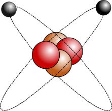
Electrons are one of three particles that make up an atom. A traditional way of looking at the atom is as a nucleus, made of protons and neutrons, and electrons. The electrons (black) orbit the nucleus while the protons (red) and neutrons (brown) are packed tightly together. (Note that this is a simplified view of atomic structure, but is good enough for our needs.)
Now, why would we care about an atom? Well, if you think about another name for hardware, electronics, you may find the answer. All the cool things we can do when designing circuits are possible becuase of the electron. Controling how and where electrons move is the goal of circuit design. So let’s have a closer look a this little particle.
Electric Fields
What’s so special about electrons? A couple of things actually…
- They carry an electrical charge
- In conductors, like copper, they are able to move freely from one atom to another (we’ll see that this is important.)
When scientists were playing with electricity a in the 1800’s they decided to assign a negative charge to the electron. Conversely, the proton was assigned a postive charge. Here is an illustration of an isolated electron and an isolated proton.
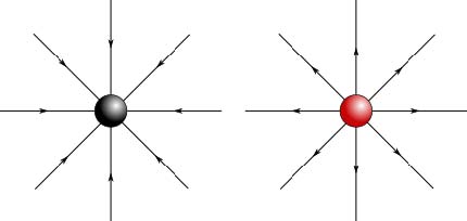
We typically draw lines as shown going into an electron and out of a proton. These lines represent the electric field produced by each particle. So then comes the question, ‘What is an electric field?’. Basically an electric field is the force exerted by one charged particle on another charged particle. What does that mean? Let’s look at an example.
We’ll bring two protons close to each other.
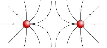
See how the electric field lines bend as the two protons get closer and closer. Those bent lines indicate that two particles are pushing each other away. So we learn a couple of things from this example.
- Two positive charges repel each other (push each other away). If we let the particles go, they both go in opposite directions to get away from each other.
- The closer the the two charges get, the harder they push against each other. You need to push harder to get two particles closer to each other.
Note that you’d get the same result if you tried to push two electrons together, they would also repel each other.
But what happens if you bring a proton close to an electron?
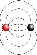
You can see that the lines leaving the proton now bend towards the electron. Also note that the arrows of the field lines point from the proton to the electron. These two things indicate that the proton is attracted to the electron. If we let these two particles go, they will race towards each other as the electric field pulls them together.
We’ll finish up about field lines with one more note. You may have wondered where the direction arrows on the field lines came from. In reality, it’s a historical thing. Again, when the guys playing with this stuff in the 1800’s were trying to figure it out, they would ask ‘How would a positive charge move if it were in this field?’. Looking at an isolated proton and an pretend postive charge, called a test charge, we get:
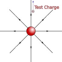
See how the test charge would move away from the proton, as indicated by the blue dashed line. The field line arrow points the same way that pretend charge is moving. Obviously, a pretend positive charge would move towards an electron, so the arrows point toward the electron.
To sum up, two same charges repel each other, while two opposite charge attract each other and the closer the charges are to each other, the stronger the force is between them. Who cares?
Voltage, the driving force
It turns out that we need these electric fields to get anything done. Take a look at the diagram below.
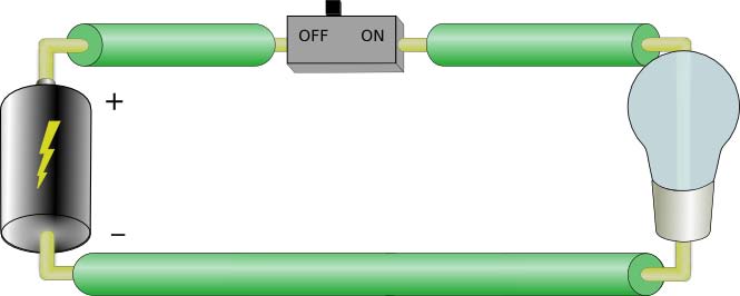
We’ve got a battery, a switch, and a light bulb. If we close the switch, we know the light bulb will glow. Why does it glow? Because electrons move out of the negative terminal of the battery and enter the positive terminal. It is the movement electrons through the light bulb that allow anything to happen.
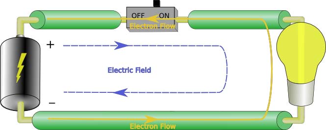
Basically, when we close the switch and electric field appears across the circuit. As we know from the what we just learned, this electric field will exert a force on the electrons in the circuit. The negative terminal repels the eletrons, while the postive terminal attract them. The voltage formed across a circuit is the result of electric fields.
There you go, that’s why we care about electric fields. They allow us to force electrons to move through a circuit to do something useful. (Actually we’ll probably need to use electric fields, or E-fields, to explain a couple of other things down the road.)
Current, on the freeway
While voltage is the driving force in our circuits, it is the actual movement, net movement, of electrons that gets things done.
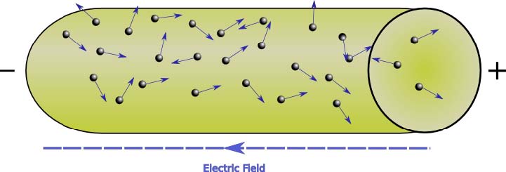
Have a look at this chunk of wire…
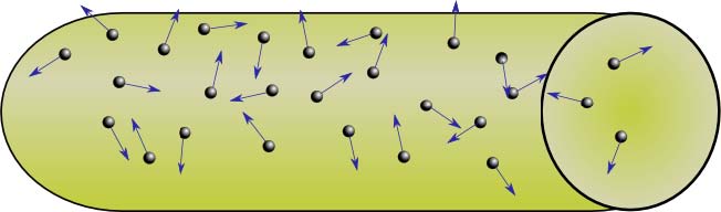
It’s been drawn to show how the eletrons would be moving if this wire just sat on your workbench. Notice how all the eletrons are just moving about in random directions. In general the movement of one electron in a given direction will be cancelled by the movement of another electron in the opposite direction.We say the net movement electons in the wire is zero. They aren’t accomplishing much here.
This is also a good time to comment about how easy it is for electrons to move around in the copper wire. You can see that they seem to be able to move up or down, left or right with little restriction. This what makes copper a good conductor. The electrons are able to freely move around and if they can get organized and create a non-zero net movement, then they can actually achieve something.
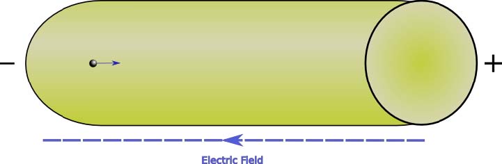
So here’s the wire with a voltage applied.
See how most electrons moving to the right. Most of the arrows lean to the right, indicating that the elctrons have a trend towards the positive terminal. Some electrons are still shown as tending to move toward the negative terminal, but there are way fewer of them, so they don’t completely cancel the majority of the electrons tending towards the positive terminal. We now have a net movement of electrons that is greater than zero. We call this net movement current and it is measured in Amperes (Amps for short). Now we can light the bulb.
Final note: Conventional Current
Okay, now that we’ve explored electrons, electric fields, voltage, and current, I’m going to tip things up on their head.
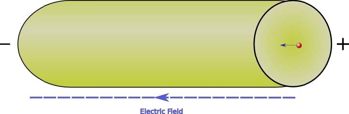
Remember the light bulb circuit above? We saw that the electrons flowed out of the negative terminal and into the positive terminal. This is the real current that flows in the circuit. But, as I mentioned earlier, when this stuff was being discovered, the physicists always used a pretend positive charge to explain things. They thought that it was positive charges flowing in a circuit. So in their circuits a positive charge would leave the battery’s positive terminal and enter the negative terminal. Unfortunately, this way of looking at circuits stuck around long enough to become the standard way of viewing things. So when we analyze a circuit, we use what is called conventional current. The current that would flow if we use pretend positive charges instead of electrons. It’s not really a big deal, it just means we draw a charge going to from the positive terminal of the battery to the negative terminal. You could also look at it this way, moving an electron from the left to the right
has the same effect as moving a positive charge from right to left. Note that we call these moving charges
current carriers.
That’s if for now. Next time: circuit fundamentals.
Sweet!