We’re finally starting to get armed with some more useful tools to allow us to understand and design some practical circuits.
Today I’m going to talk about another of Kirchoff’s contributions to circuit theory, Kirchoff’s current law. To beign we need to define something called a node within the circuit. Basically a node is where two or more wires connect to each other.
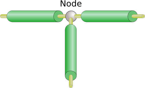
Since our wires have the same voltage along their length, all terminals attached to the same node will be at the same voltage. (We also call voltage as potential, so we could say that all terminals connected to the same node are at the same potential.)
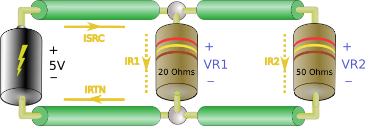
Now what does Kirchoff say about current? Have a look at the next circuit.
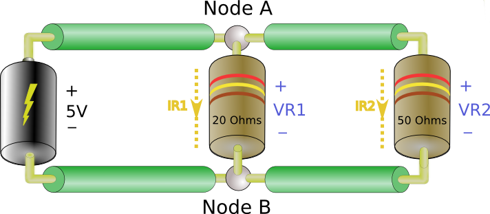
We have one source and two loads. Instead of lamps, we’ve used a component called a resistor. You’ll become very familiar with resistors. This circuit looks a little different than previous ones. We know from above that the top terminal of each resistor is at the same potential (voltage) because they’re both connected to node A. Also both bottom terminals are at the same potential because they’re connected to node B. So we can say 


Okay, that’s great, but what now? Now we come to Kirchoff’s current law. He says:
All current’s flowing into any node must be equal to all current flowing out of that node.
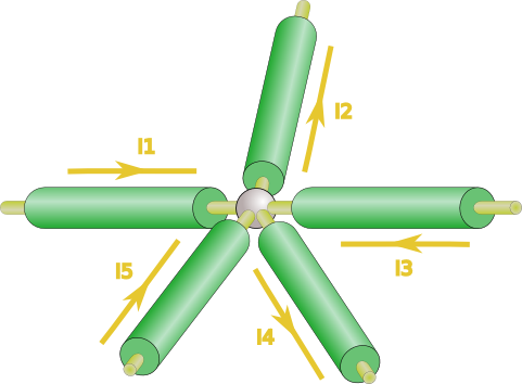
Here 


So what does that mean for our two resistor circuit? Let’s see…
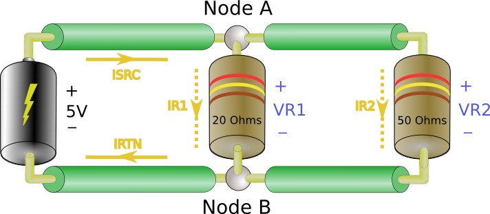
From Kirchoff’s current law we now know that

By the same law we see that 

Now, you may well be asking how will this help us in designing circuits? I know I was wondering such things when I first learned this stuff. Well, it turns out this is a useful tool in understanding our next topic which is a bit more practical.
Basic Circuits: Starting at the beginning
We’re going to discuss something called circuit topology here. Circuit topology is really just a fancy way of talking about how components are connected to from a circuit. We’ve already seen the two basic toplogies we’ll discuss here, series and parallel. Have a look…
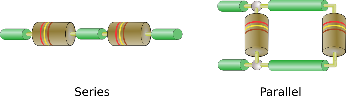
It doesn’t take much imagination to figure out why they’re call series and parallel. So why are these two topologies important? That’s what we’re going to look at now.
We’ve seen that we can use Ohm’s law to find unknown voltage, currents, and resistances. Now we’ll use that and Kirchoff’s laws to find something called equivalent resistance. To get an idea of what we call equivalent resistance think of a battery connected to a circuit. Some current flows out of the positive terminal of the battery, I, and that terminal is at some voltage, V. From Ohm’s Law we know that 
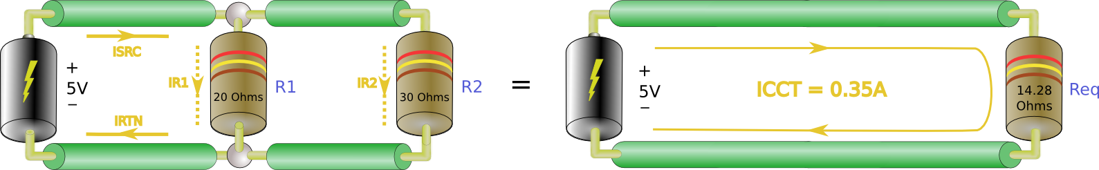
Let’s look at one example starting with a series resistance.
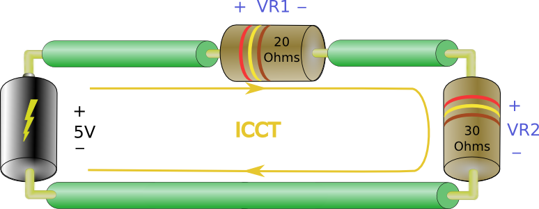
Actually we’ve aleady seen this problem. Here the current through each resistor is the same, ICCT, from Kircoff’s Current Law. According to Kirchoff’s Voltage Law (KVL) we know that 


which gives:


Remember we just said that the current out of the battery divided by the current out of the battery is the equivalent resistance, 

In this case the equivalent resistance is simply the sum of 


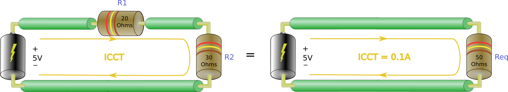
So in general the equivalent resistance of a bunch of resistors in series is just the sum of all the resistor values. Just add ’em all up.
Note that the value of
Now what about the parallel case? ….
As stated above, 


Now all we need to do to find Req is….

Note that the value of
You’re probably thinking, ‘Hey, I don’t wanna have to solve all those current’s and whatnot just to get an

Try it with a calculator and the values from our parallel circuit. So if you have three resistors you’d get:

For four:

This is reasonably easy to do on scientific calculators.
Before continuing to a final example I’d just like to clarify one point that may not be obvious. When we refer to equivalent resistance, we’re talking about the resistance that the source ‘sees’ looking into the circuit. In the previous two examples we showed that
Now, here’s one more example to get us home.
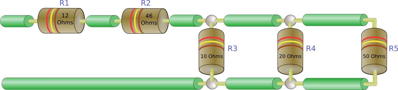
All we want is
It’s best to start with the equivalent resistance for just the parallel resistors.


Then 

In most cases I like to reduce any parallel resistances to an 
So far we’ve developed a quick theoretical foundation to understand how this all boils down to electrons. Then we’ve moved to some basic circuit theory in Kirchoffs laws. We used this theory to gain an understanding of Ohms law and to figure out how to analyze some circuit topologies. Finally we discovered how to figure out equivalent resistance. So far you may still be scratching you’re head about how most or any of this applies to actual circuit designs. I’ll give you the low down on what I use.
In general I don’t think much about atoms or electrons. I don’t really consider electric fields (well not for circuit design anyway). I do use the ideas behind Kirchoff’s laws, not to calculate values, but you need to know that the total voltage around a circuit is zero (all sources balance by all loads). Even more important, I use Ohm’s law all the time and frequently need to calculate an equivalent resistance. You’ll see soon that we come back to these basics time and again.
Next time we’ll start looking at basic components: resistors and diodes.
This is really good basic presentation in Hardware circuit design.
It would be really good if you could provide knowledges about switch mode power supply design, Amplifiers, power electronics, switching circuits etc.
Thank you for such an amazing content. Looking forward to seeing more of it!
Any idea when you guys would be posting a Lesson 4? *Eagerly Waiting* 🙂